4.10.2 Apollo 6
The next unmanned mission in the Apollo program was Apollo 5. Its aim was to test the LM in space conditions, and provided the first firing of an engine with a throttle in space. It did not have a full Saturn V set up, and did not include cameras in the mission profile. Its mission report can be found here.
The next full Saturn V workout was Apollo 6, launched on April 4th 1968, its progress largely unnoticed thanks to the assassination of Martin Luther King.
Apollo 6 was again a brief mission lasting only 10 hours, and was mostly an LEO mission. Its main aim was to test the ability of the Saturn to carry out a TLI burn, measure radiation levels in the Van Allen belts, and to test the CM’s re-
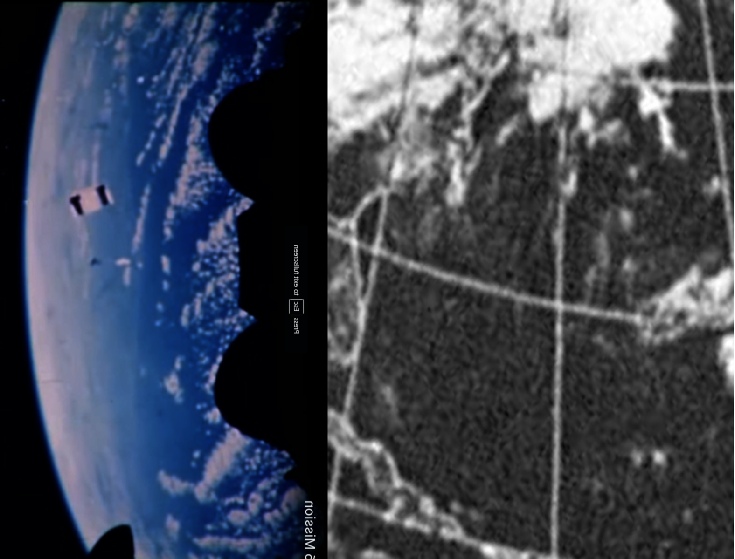
As with Apollo 4 we can have a look to see whether the footage matches what should be there. Figure 4.10.19 below shows a small section of the ESSA photograph from that day compared with a screenshot from the separation video.
A basic summary of the photography process is given in the photography index linked to above, but a more detailed description of procedures is given in the Science report on the 70-
The Shenk et al. papers attempt to use the images taken by Apollo to try and identify and classify clouds and to see how this compares with similar attempts made using ESSA and ATS imagery. Unsurprisingly, the general conclusion is that high resolution full colour images capable of being viewed stereoscopically (thanks to the close time interval between photographs) are more useful.
As with Apollo 4, there is little point in re-
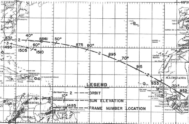
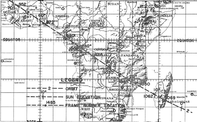
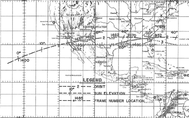
What is worth a cursory glance is to see where the photographs fit globally, compared with where the Apollo orbital track shown here puts them.
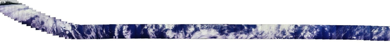
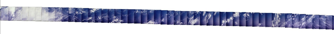
To do this, each image recorded in the AIA link was joined with the next one by matching cloud patterns. The first part of the sequence consists of the Earth horizon, after which the camera pans down and begins taking photographs from a near vertical perspective. Joining one photograph to its neighbour is relatively straightforward, but it is worth mentioning that no rotation of the images was carried out to fine tune the resulting montage. Two extremely long photo compilations are the result, and these are shown in figure 4.10.21. The reader is referred to the article referenced above, where the authors carry out a similar exercise.
Figure 4.10.21: Photomosaics from Apollo 6 orbits. The top 2 are from the pass over America, the bottom 4 the pass over the Atlantic and Africa. All travel west to east. Larger versions of the two entire passes are available here and here
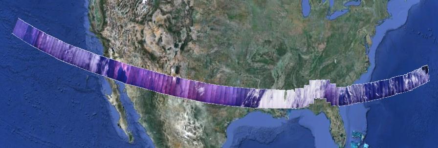
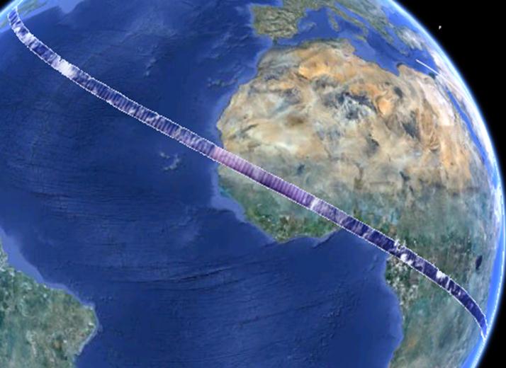
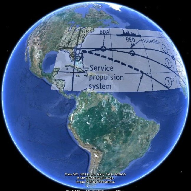
Figure 4.10.22 shows these mosaics placed in Google Earth, aligned by the location of the coasts (where visible). As the images have been aligned laterally with no rotation applied.The positions are not 100% accurate, but they are close enough. Central Africa’s colour is related to the lighting conditions at the time of the photography session.
How do the Apollo photomosaics compare with the satellite mosaics? Figure 4.10.23 shows the relevant parts of ESSA’s imagery.
It’s quite easy to identify the cloud formations in the the two sets of images even without my added arrows, but some people refuse to see what’s in front of them!
The video footage is more difficult to identify, and is not helped by the amount of footage purporting to be Apollo 6, but is actually from other missions. There is, for example, footage showing S-
The mission report describes the video operation:
“The 16mm movie camera operated through the left rendezvous window during the launch and entry phases...the camera photographed the departure of the boost protective cover and the launch phase until insertion, and then command module turnaround and plasma flow during the entry phase.”
This video, Apollo 6 film 5, does seem to be from Apollo 6 as it matches what the mission report describes. Nothing much is discernible for the first part of the video, but at around 30 seconds we can see the departure of the boost cover and the view shows the Earth’s horizon through the CSM window, with the sun clearly in view. After some rotational manoeuvres the window swings down to show the surface below. It’s obvious from the direction of movement that the video is upside down, as the surface below the CSM is moving from left to right, when the apparent movement should be right to left.
The next question is: what does the video show? As the camera began operating 70 seconds after launch, and the boost cover disappears after about 30 seconds, it is only a couple of minutes after launch, so the view should be of the mid-
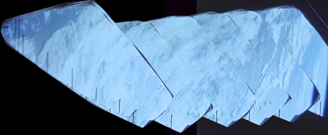
The orbital height at this stage means we are looking at a relatively small section of Earth in any one frame, but by stringing several screenshots together it is possible to extend that view to a more useful size. This is shown below in figure 4.10.26.
This gives us a longer path to look at, but the path itself is still only a hundred miles or so wide. The clearest image of the Atlantic (and the nearest in time to the launch) comes from the photographic analysis referred to earlier and the ATS-
Figure 4.10.27: ATS-
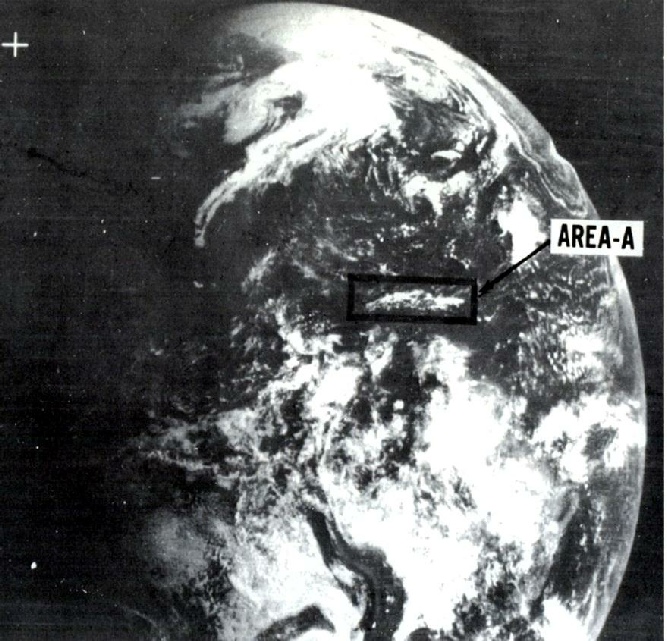
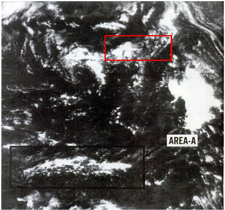
From the preceding images, it looks as though the area covered by the video is shown in a more detailed close up of the ATS-
The area highlighted by the red rectangle is on the flight path, and has a solid mass of cloud followed by the more broken cloud trending in the appropriate directions. The match is not exact, but the image was taken nearly two hours after launch, so a small amount of change is to be expected.
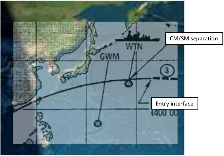
The second half of the video shows the re-
Re-
The area of sunlit ocean covered by the returned spacecraft must therefore be between China and the re-
The track covering the area on the ESSA image (figure 4.10.30) dated the 4th would have been just after midnight on the 5th.
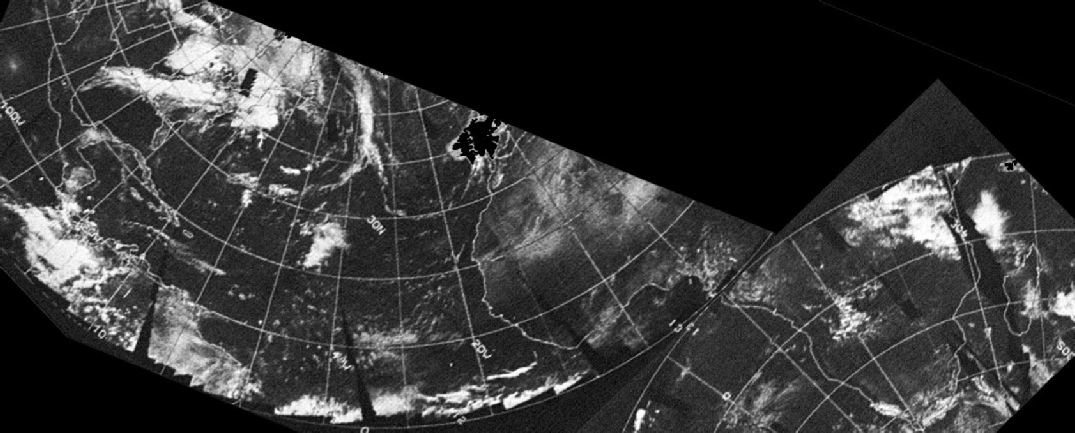
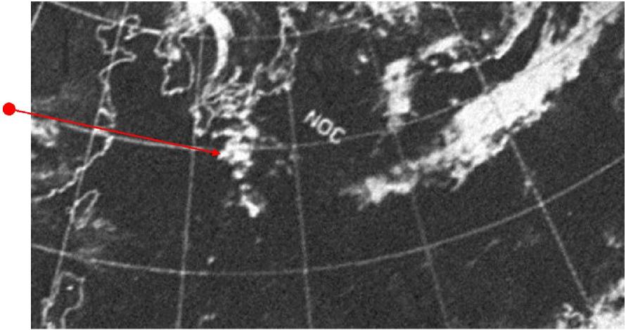
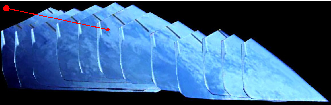
Figure 4.10.31 shows a compilation of screenshots from the re-
Figure 4.10.31: Compilation of screenshots from Apollo 6 re-
The screenshot compilation starts with a darkened area, so obviously this is close to the Chinese mainland, and the cloud on the right is close to the landing zone (it is difficult to tell, but the re-
Having launched and tested the Apollo hardware and procedure without the presence of people, it was time to launch some actual astronauts up there: Apollo 7.


The separation events are all recorded as being east of Florida, and you can see the US landmass in the background. The cloud masses aren’t as clear as in Apollo 4’s imagery, and it wouldn’t be prudent to identify specific clouds here.
One magazine of photographs was taken, successfully exposing 373 colour photographs Figure 4.10.20 shows the path covered by the photographs (Source: AIA). The Apollo Image Atlas shows all the images (AIA), but they are low quality reproductions. The documents showing the satellite photographs for that date in question can be found here and here.
ESSA shows that for the most part the US is cloud free for the bulk of the orbital photography with the exception of the Gulf states, where there is a thick band of frontal cloud, to the east of which is lighter cloud cover. The Atlantic has a few areas of dense cloud cover off the US east coast and some frontal bands, but otherwise has relatively little cover. The African coast has light cloud but the area of west Africa overflown by the mission is mostly cloud free, and the only significant cloud is the east coast and towards Madagascar. Apollo’s images show the same pattern.
By way of comparison, the ATS-
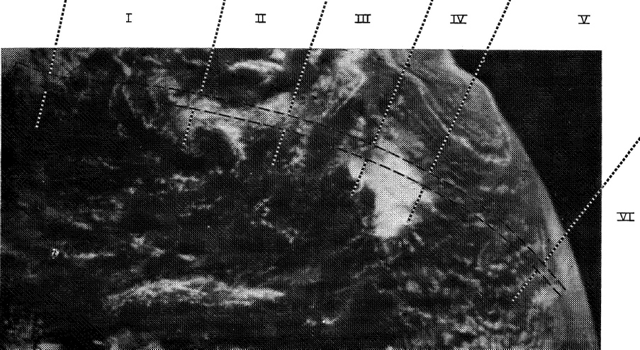
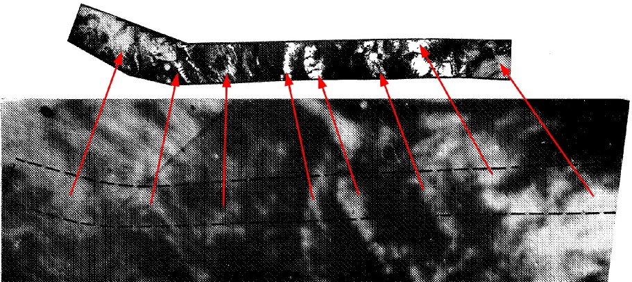
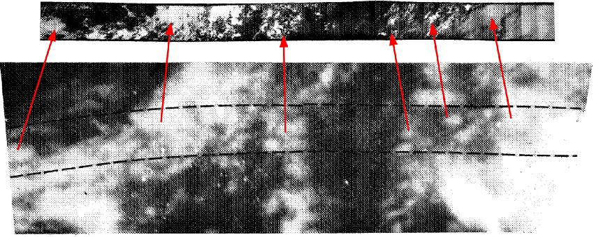
Figure 4.10.24c: Sections ii and iii from figure 4.10.24a comparing Apollo 6 images with ATS-
Figure 4.10.24b: Section i from figure 4.10.22a comparing Apollo 6 images with ATS-
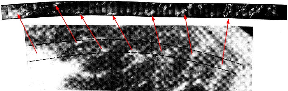
Figure 4.10.24a: ATS-
Figure 4.10.19: Separation footage from Apollo 6 compared with ESSA satellite image
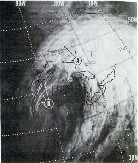
Figure 4.10.23: ESSA images of Earth covered by Apollo 6 photography sessions
Figure 4.10.20: Orbital path of the photography sessions taken by Apollo 6. Sources given in text
Figure 4.10.22: Photomosaics from Apollo 6 orbital photography placed on Google Earth.
Figure 4.10.24d: Sections iv (part) to vi from figure 4.10.22a comparing Apollo 6 images with ATS-
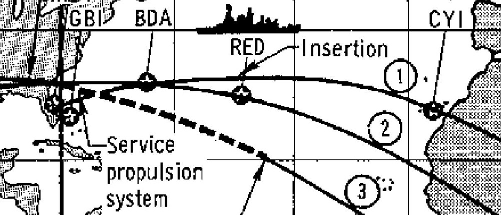
Figure 4.10.25: Flight path to orbit insertion, taken from the Mission Report.
Figure 4.10.26: Compilation of screenshots from Apollo 6 orbital footage. Source given in text.
Figure 4.10.28: Zoom of ATS-
Figure 4.10.29: Earthview depiction of terminator location at 21:40, 04/04/68 combined with mission report flight plan shown point of re-
Figure 4.10.30: ESSA view of re-