Of the images listed above, the best is AS10-
It is of comparable quality to the orbiter image, but it is still woefully lacking in detail compared with the LRO photograph and the 1978 map.
There are no other possible sources for the 1978 map apart from Apollo 11 images -
The only other possible source for the photogrammetric map are the Apollo 11 images taken from the surface, so let’s have a look at what some of them show.
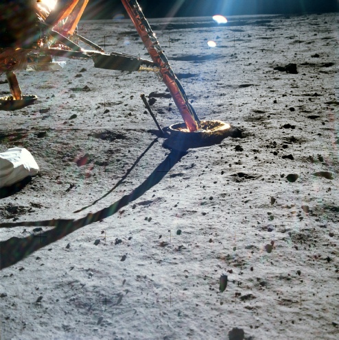
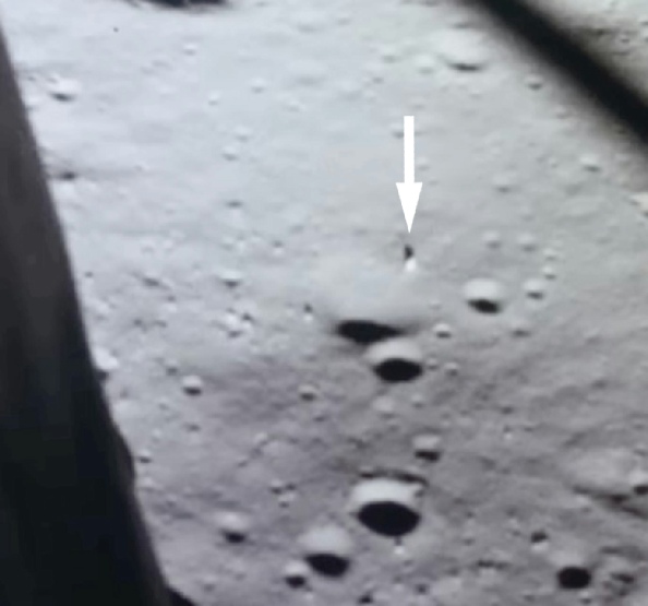
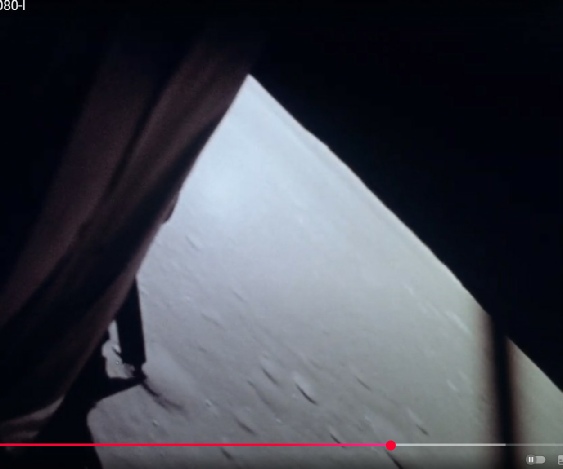
The first one shows the view taken by the 16mm camera positioned in the lunar module window on the way to landing shortly before ‘contact light’.
This image is not from a digital source, but is a scan of an image published in Life magazine in August 1969 (see here). This is important because there can be no accusations of it being digitally manipulated or altered after the fact. It is an original published 40+years before the LRO image. The landing sequence itself is available in many places, and here is one youtube example.
The photograph us shown with a correctly oriented LRO crop. The lunar module has been left in for reference in the LRO view, but the actual extent of the 16mm still does not quite reach that far.
I’m hoping that it even the most myopic of morons will be able to see that the photographs are showing exactly the same place, down to the smallest rock and crater. Everything is in the right place. I’ve even added some pretty arrows to help.
Everything.
The only thing missing from the 16mm still is the trail from the lunar module to Little West crater, which would run almost parallel with the window frame.
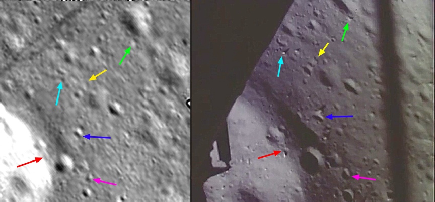
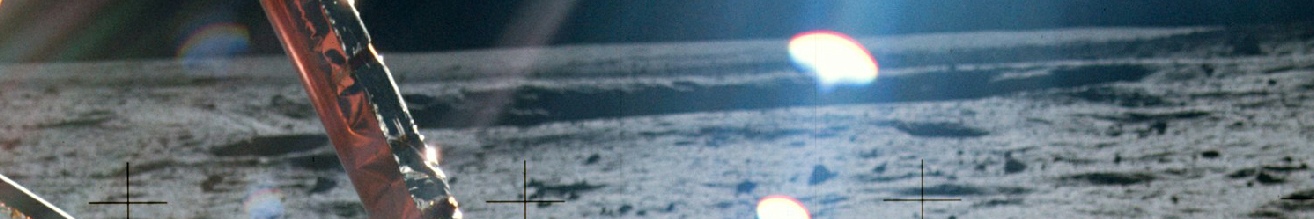
Can we continue this further into the descent? Yes we can. The image below is from just a few seconds further on, and the LM as begun to pass closer to and over the crater in the foreground of the image above, and his rotated slightly as it makes adjustments ready for landing.
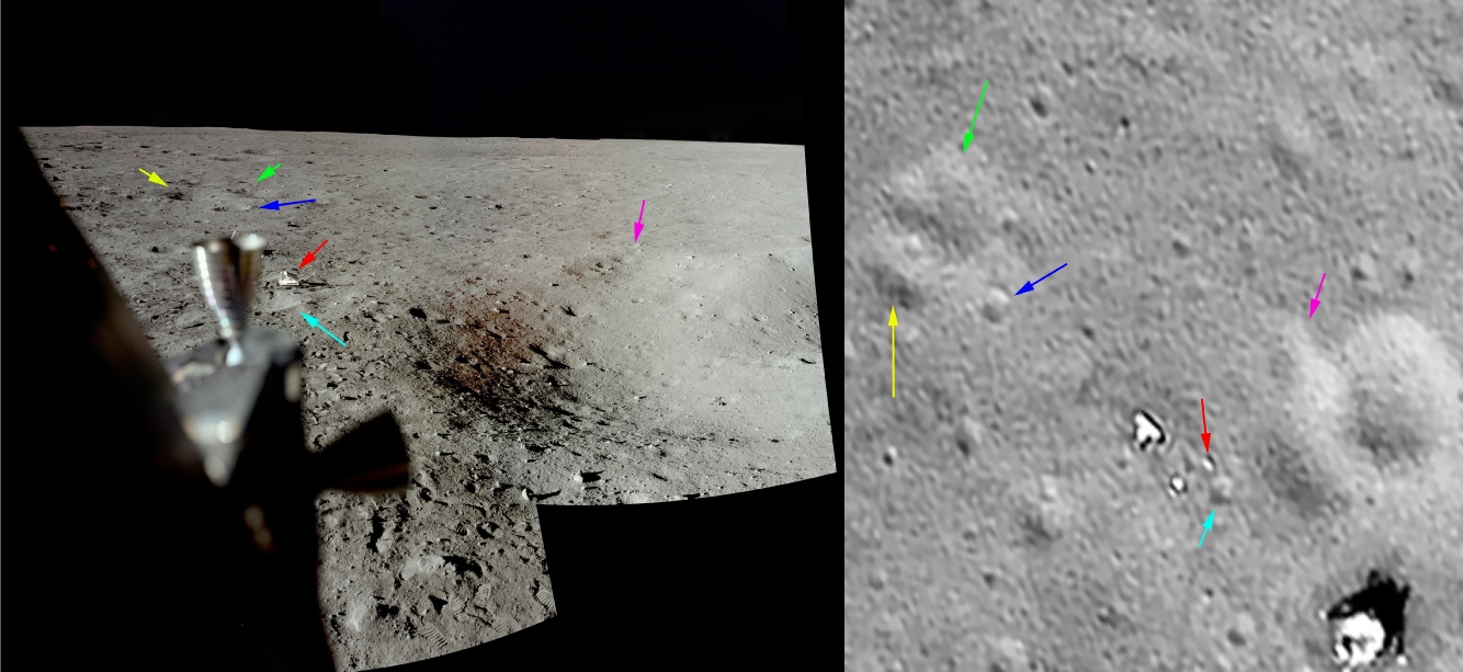
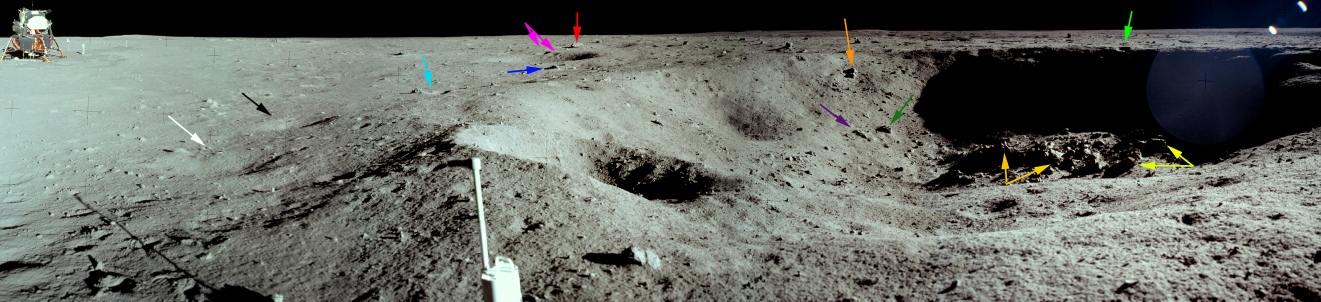
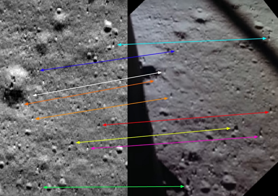
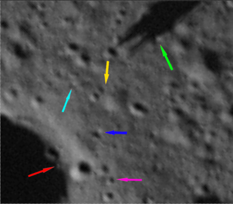
The photomontage is looking north-
To the left of the camera itself but not quite level with it is a small crater that is visible just north of the end of the disturbed soil zone on the LRO photograph. To the right of the camera and again not quite level with it is a larger crater visible in both the Apollo image and the LRO/OHRC. Continuing towards the right of the Apollo image just above and to the right of the thruster s a larger crater, on the edge of which is much smaller one (just above the crater), and again there is a corresponding pair of craters in the LRO/OHRC.
In the top right corner of the LRO/OHRC images is a larger crater with a smaller on the lop, and this can be seen in the distance above the thruster in the Apollo photograph. Level with that in the centre is another matching crater, and so on and so on.
All around the Apollo photograph shown above are craters that are also to be found in the LRO?OHRC view of the same scene, craters that are not to be found in the orbiter view. The OHRC is also very good at picking out the larger matching boulders.
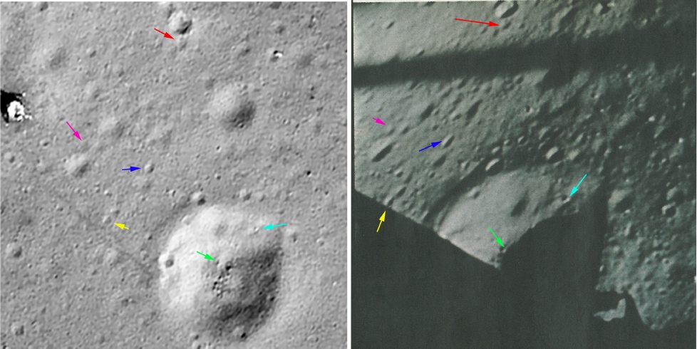
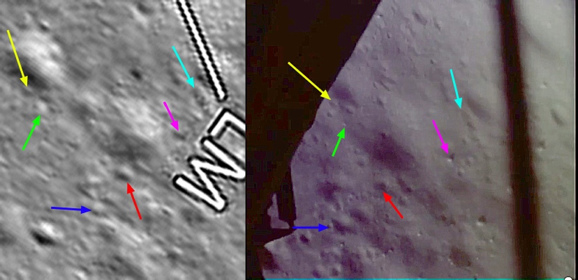
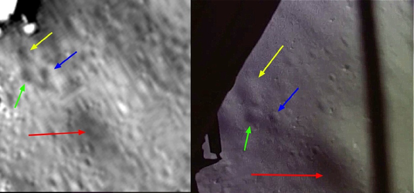
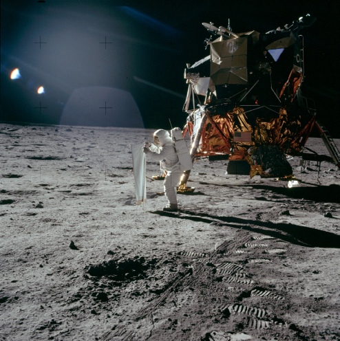
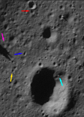
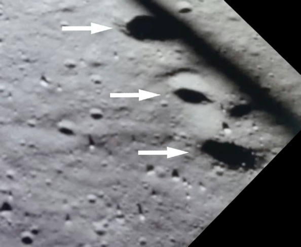
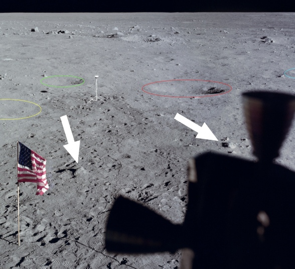
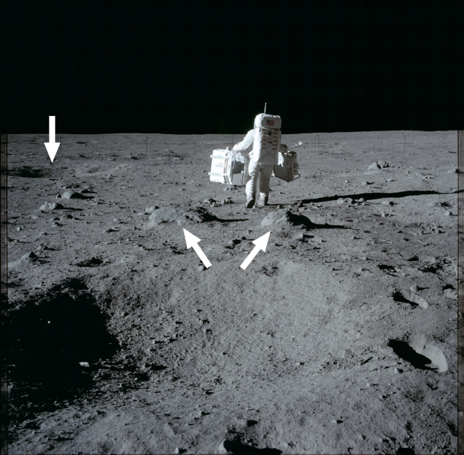
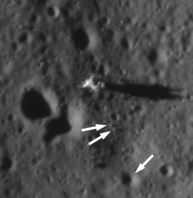
Looking through the adjacent window we have a view of another piece of Apollo hardware, the laser ranging retro-
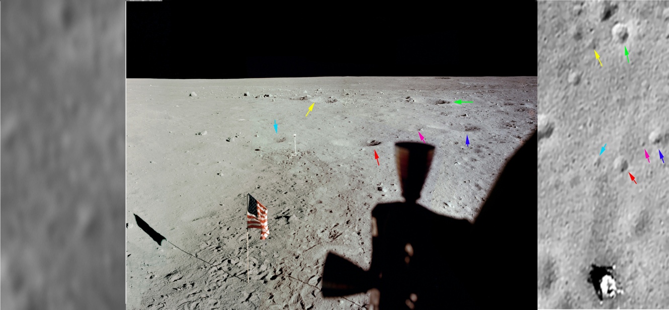
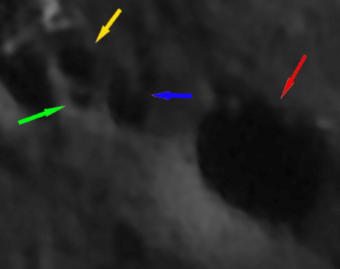
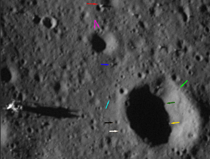
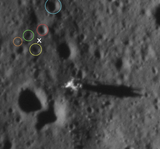
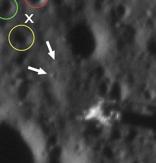
The LRRR equipment (red arrow) can be seen just to the right of the sunlit thruster in the Apollo image, and just below centre in the LRO view. It is installed near the edge of a 3 shallow overlapping craters, the largest of which is not quite covered in the panorama above, and the centre of which is identified by the magenta arrow. The disturbed ground around the LRRR (which, you will notice, is correctly oriented in the LRO view) is visible in both shots. The shallow craters can be made out in the Lunar Orbiter and Apollo 10 images -
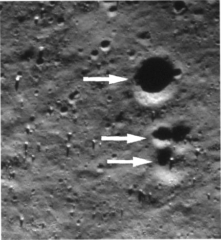
At the edge of the LRO version, in a direct line between the LRRR and the lunar module, is another set of shallow craters that can also be seen in the Apollo photograph (above the sunlit thruster). This group consists of a pair of larger shallow craters (yellow and green arrows), with a smaller, deeper crater between them and a deeper crater (blue arrow) just off them in a line towards the LRRR. If the Apollo image is zoomed in closely, these same craters can be seen in the correct place. The larger shallow craters can just made out in the Lunar Orbiter image, but not the Apollo 10 photograph.
As with the first window view, the more the photographs are examined, the more details can be found that are in both Apollo and LRO viewpoints, but not in the earlier views of the landing site.
Apollo 11’s actual landing site is well documented at the Apollo Lunar Surface Journal, with a variety of sources showing that site as viewed from the Lunar Orbiter and Lunar Reconnaissance Orbiter (LRO).
The LRO website is here, but by far the best analyses of their images of Apollo landing sites is by ‘GoneToPlaid’. There is a particular breed of idiot that argues that even the LRO images are fake, and that the Apollo hardware, foot and vehicle tracks evident in these photographs have been added. Aside from well argued critiques of that idea (to whit: the original LRO images are available to all in their original format), what will follow shows that they would also have had to fake every rock and micro-
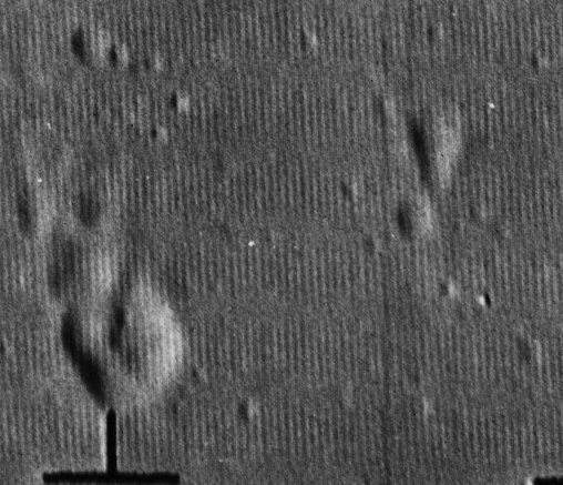
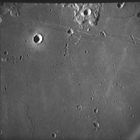
It’s interesting to compare this image with one obtained by Ranger 8, an unmanned probe launched in February 1965 that transmitted TV pictures back to Earth as it was approached what is euphemistically known as a hard landing, slamming into the moon about 70 km north-
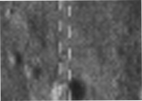
As it did so, Camera B just caught the landing area, and this is shown below in both the original image and a zoomed crop covering roughly the same area as the Lunar Orbiter photograph.
Two things should be clear here. Firstly, the 1978 map shows a high degree of correspondence with the LRO, from the smallest crater to the lines of footprints.
There are only two possible sources of information for the location of these craters, boulders, and human artefacts. Firstly, the Lunar Orbiter images, which as we know from what has been shown above are not adequate for the purpose, and Apollo photographs taken by people.
Of the Apollo sources we first have to discount the use of the Apollo images that did not land before Apollo 11.
The reader is referred to this section of this website which contains Google Moon kmz files showing the location of Apollo photographs taken in lunar orbit.
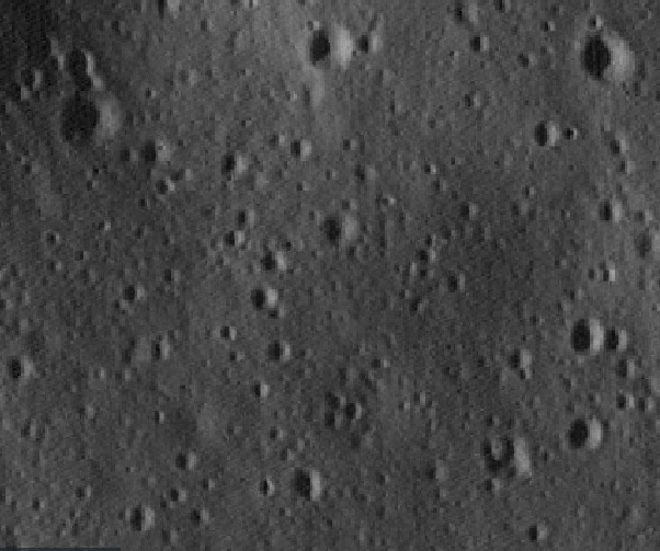
Apollo 8 did not fly over Tranquillity Base, but during Apollo 10, the following images were taken of the landing site looking vertically down:
So taffy, your claim that there is no raised crate rim is proved wrong by photos from the ground and orbit, and you’re an idiot.
Another interesting and challenging bits of work came from yet another conspiracy blinded nitwit making a ludicrous and unfounded claim, expecting it to go unchallenged and just be accepted as fact. The claim was that no rocks were visible in the Apollo 11 EVA TV broadcast, so there was no way that anything could be identified from the (admittedly poor) TV images.
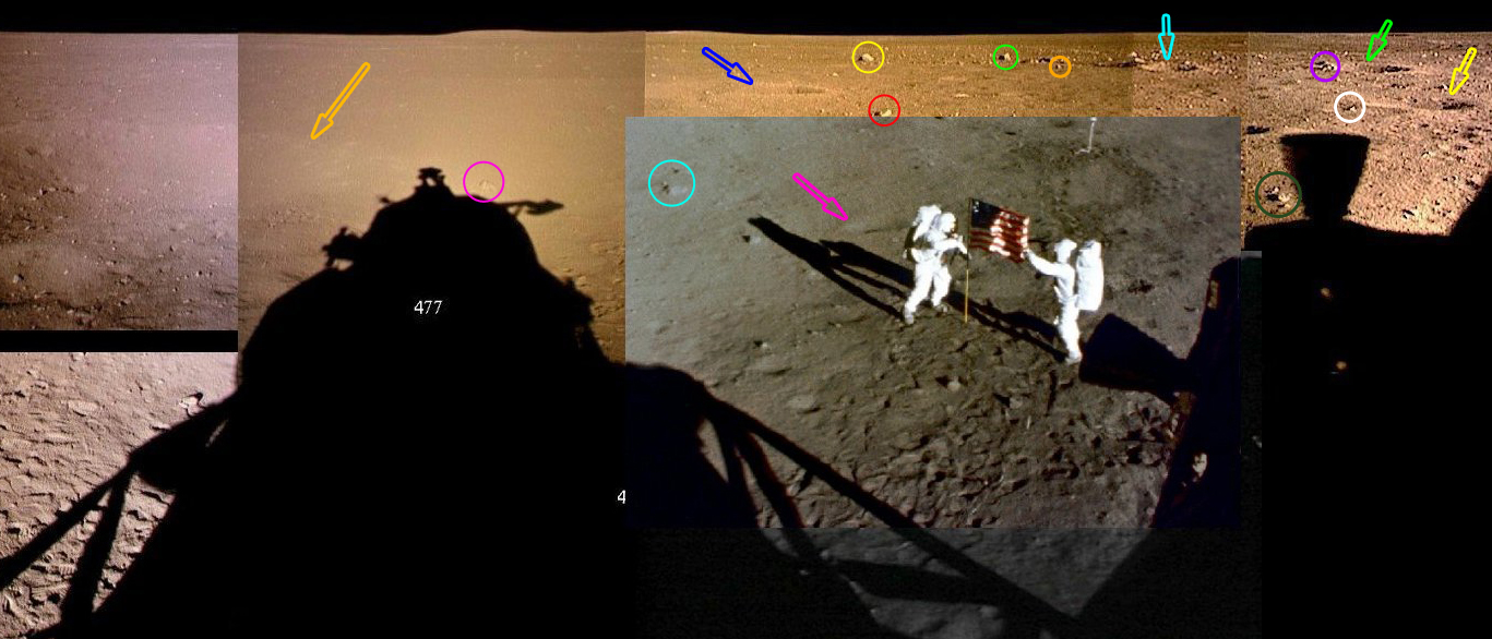
Most people are familiar with either the view of Armstrong stepping off the LEM now, or the static view of the LM from the camera’s final position 100 feet away from the lander as the crew went about their business. However the full TV broadcast, seen by millions around the world, also featured a series of views around Tranquility Base after it was carried from the LM to its broadcasting position. Here’s a link to just one of the many sources of the broadcast in question.
As the camera pauses on each of those views, we can attempt to compile a rough panorama and see of we can identify the features in them. To help us in our quest we have a couple of other pans, one from the LM with an added frame from the 16mm camera and the other taken by Buzz just away from the LM. The former is useful as it gives a bit of height to help identify things, but doesn’t quite cover the whole scene viewed by the TV camera. The latter is a good comparison of the view from the ground and we also get a good indication of parallax showing the size of the area being covered. We even have a third that we can use a as comparison, taken just to the west of the LM,
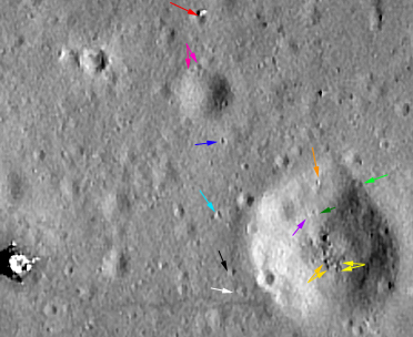
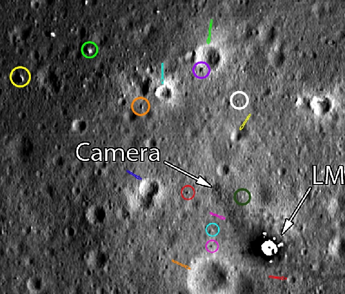
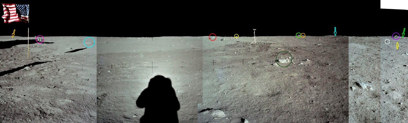
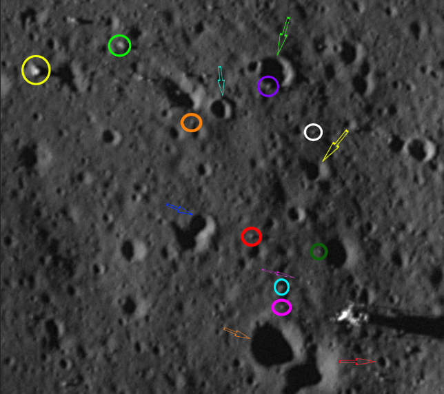
So, having done that let’s see if we can , by a cunning selection of arrows and circles identify features on the set of views in comparison with the LRO’s image of the site. The area covered by the TV pan is quite wide so I’ve split the view into two, and I’ve cropped the pans to remove areas that aren’t covered. Some features can be made out in the pans that can’t be seen in the TV view, but I’ve identified them partly because I can, and partly because it helps to locate things seen on the TV footage.
Pictured above left is the same area covered by the LRO view, and above right the OHRC.
Unsurprisingly, all of the features picked out in the Apollo panorama can be seen in the satellite views, and many more besides (I ran out of colours). Not all of the features inside Little West are visible in the OHRC image, and the dark green arrow is showing the shadowof a rock rather than the actual rock.
I will grant that the precise rocks picked out in the centre of Little West crater in the LRO image could be out by a pebble or two, but I think you get the idea.
What is clear is that the LO view does not show the detail visible in the modern probes, particularly in terms of the smaller craters and rocks, and the Indian and US probes are in complete agreement.

Feel free to cross check on the other panoramas to see how they match up, but trust me, they do.
One particular rock delayed matters with this exercise for some time, and that is the seemingly split rock standing proud of the horizon in the TV stills and also the ground level pan (and others). Once this one was confirmed, the others fell into place.
So, not only can you identify rocks in the TV footage, these rocks also appear in many different photographs taken on the surface and in the satellite images.
We’re not quite done yet -
The image shown below is the LRO view of the landing site (centre left), the LO5 view (centre right), the OHRC (right) and the first frame obtainable from the 16mm magazine. I’ve used a DVD version of the footage, but you can find it here -
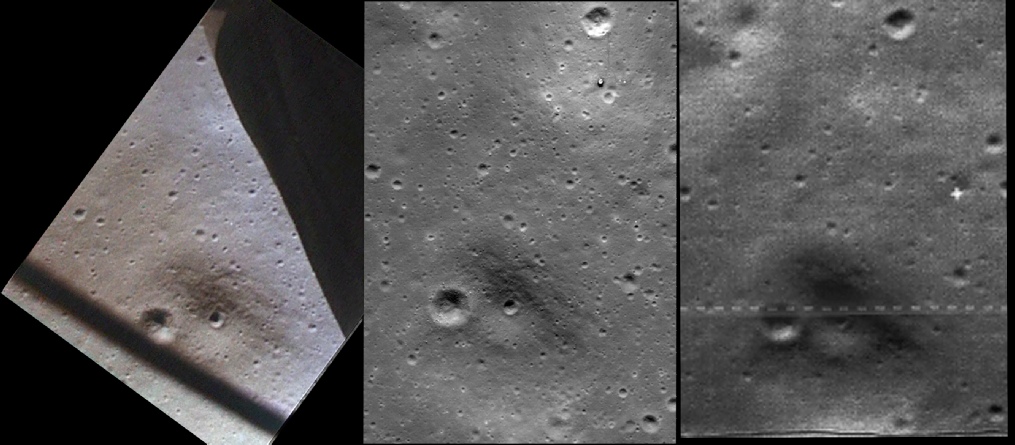
I’ve changed the orientation to make it fit the page better. For people in denial, West Crater is the large bright one right of centre at the top of the view.
As you would expect from a higher altitude view from the ascent module, on the face of it the LO5 image has done a good job of showing what’s in the 16mm frame, and you can make out many of the craters in all three shots. However, of we zoom in a little closer -
Well, the broad features are there, and you can still make out a lot of craters in the LO5 image, but you’d have to blind to refuse to admit that there is a marked reduction in the number of features visible. Can we go in any more?
Well, yes we can, I’ve rotated the image again to fit the page, and in this case the Apollo image is in the centre, the LRO on the right and LO5 on the left. By now the LO5 image has reduced to just the two larger craters, with odd smaller one here and there where they are deep enough to produce enough shadow. The Apollo 16mm still (and let’s not forget this is one frame of a long film) has enough resolution to show details within the craters, as well as other much smaller craters.
It’s a pity that the camera couldn’t swing just a tiny bit more to one side or it would have shown the LM. The cropped version below shows that the location of the TV camera is only just behind the edge of the ascent module window frame -
Looking pretty good so far. The existence of the trail in the LRO view identifies this as Little West crater beyond doubt, and the OHRC is very good at picking out the prominent boulders.
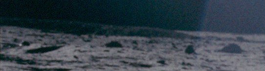
The LM descends ever closer, and a few seconds later we can take another snapshot.
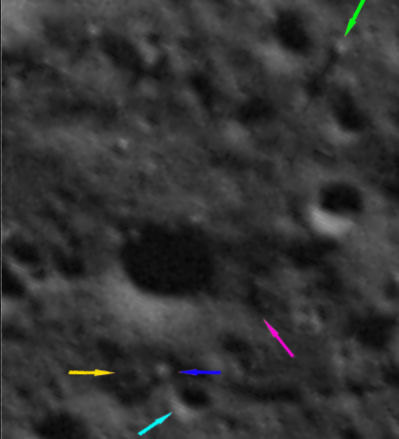
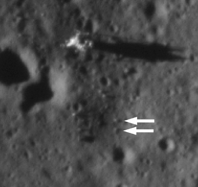
In this example I’ve used the green arrow to point to the same feature as the preceding image, a rock standing proud of the surface. The yellow arrow is absent from the OHRC image as it the crater it identifies is in shadow
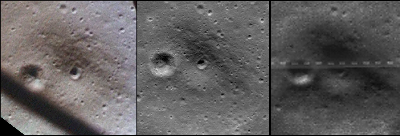
It’s fair to say that the ability of the LRO image to resolve surface details is diminishing, but we can have one more go at least while the OHRC holds out.
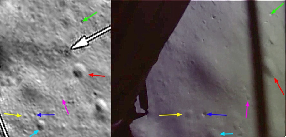
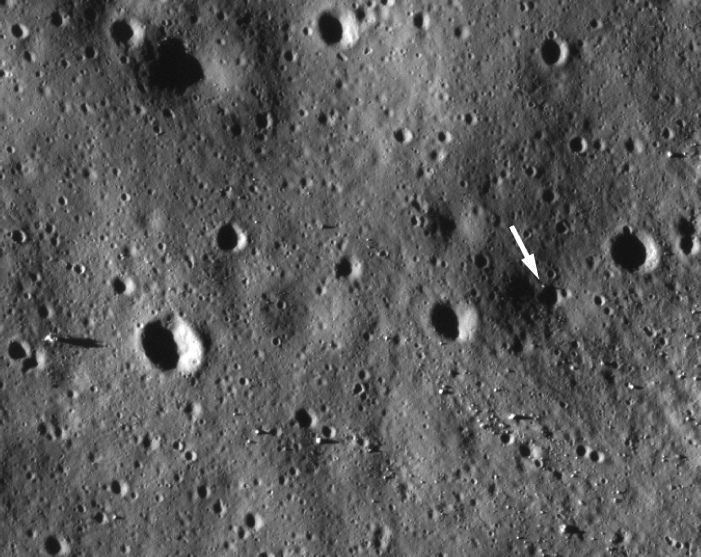
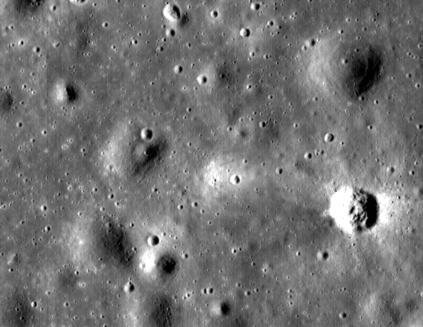
We are now at the point of just picking up some dust (you can see a light stripe in the bottom left of the 16mm frame), and while details are beginning to be lost on the LRO view it is still possible to make out that the crater marked by the red arrow is the one next to where they would stand the TV camera (the white arrow from the original LRO image), and we can still make out rocks and small craters in both views that will also be seen in the still images, TV broadcast and definitely not in the Lunar Orbiter photographs.
The final image in this 16mm descent sequence is just 9 seconds from Buzz uttering the words “contact light”, indicating the the probes on the end of the LM ‘feet’ have touched the ground.
I can say with certainty that the crater identified by the red arrow is the same can be seen in the previous image because I have watched the footage. The other craters are more by deduction than clear identification, but they seem to be in the correct place. Any more than this and we are well beyond the limits of the LROs resolution, but we have definitely followed the Apollo 11 down to the ground and identified features that were not known about prior to landing.
The deeper shadows in the OHRC view are more helpful, and support the LRO and Apollo imagery.
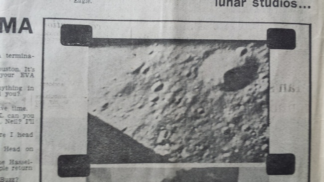
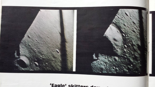
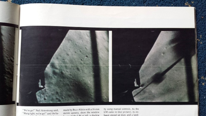
We can also be certain that they haven’t been doctored after the fact, because images from this 16mm footage appeared in the popular press at the time. Pictured below and right are some examples from my own personal collection.
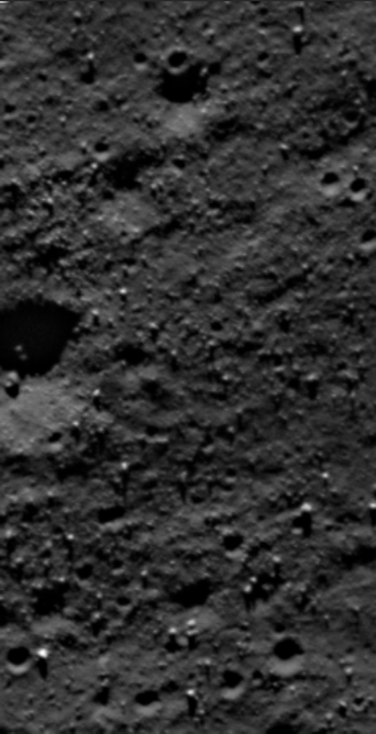
The Orbiter image does show the same broad features as the LRO version, but it should be blatantly obvious that it does not show the surface in the same level of detail. It is certainly not possible to determine individual boulders or any details within the craters. The OHRC view is more detailed still. It’s worth pointing out that the lack of obvious trails in the OHRC view is again a product of lighting -
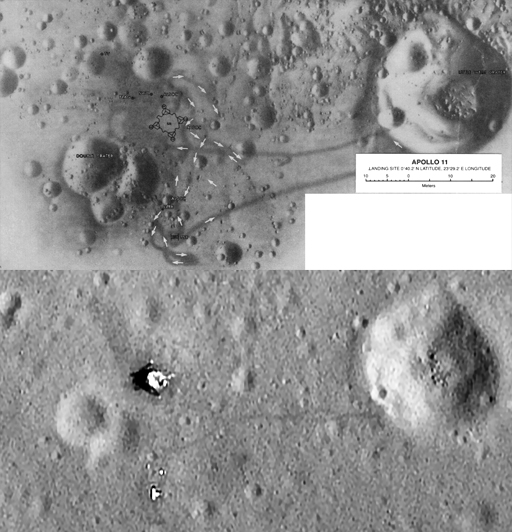
Now let’s have a quick comparison of the same LRO image with a photogrammetric map from 1978 (see below).
So even a 16mm video shows features that only the LRO would capture much later, and it could only have done this in one way: just like the photographs and TV, they had to be there.
The Apollo Detectives (they are no such thing) have also turned their attention to the ascent footage, and have tied themselves in knots trying to crowbar in their “theory” that the initial ascent was filmed at a recreation of some sort of the ground, and then (when the footage changes from 12fps to 6fps) switches to lunar orbiter footage.
Well, if you take the ascent footage at the point where it changes speed and compare it with the LRO, let’s see how they compare.
We have another interesting aspect of the landing,namely that they landed long ie past the intended landing zone (covered at the top of this page) thanks to the presence of air in the docking tunnel between the CM and LM that gave it a little acceleration when they separated.
Before the arrived at the eventual landing site, Armstrong initially wanted to head to a crater they had already unofficially named ‘West’. Armstrong couldn’t land there, because as we all now know he reported this from the scene:
“Hey, Houston, that may have seemed like a very long final phase. The Auto targeting was taking us right into a football-
So we have a couple things to look at here. Is there a massive boulder field around West crater, can it be seen in the landing footage, and are those boulders visible in the lunar orbiter image?
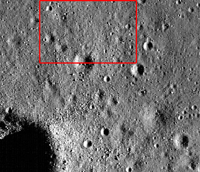
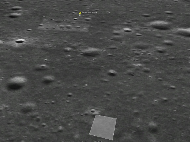
Firstly, here’s a screenshot of the area north and west of West crater, which is in the bottom left. The area outlined in red is covered by the next part of the analysis, and Lunar Orbiter’s view of the same area is shown next to it.
Should be pretty obvious from that there are quite a lot of boulders, and pretty big ones at that. The LM is actually overflying right to left along a line 1/3 of the way down the image.
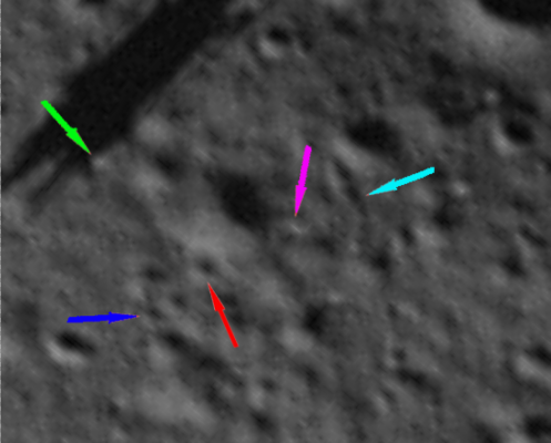
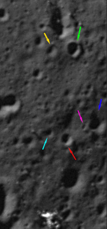
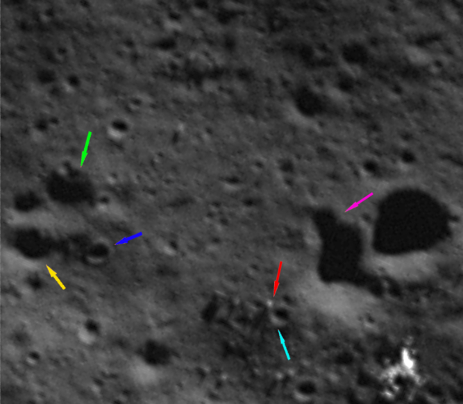
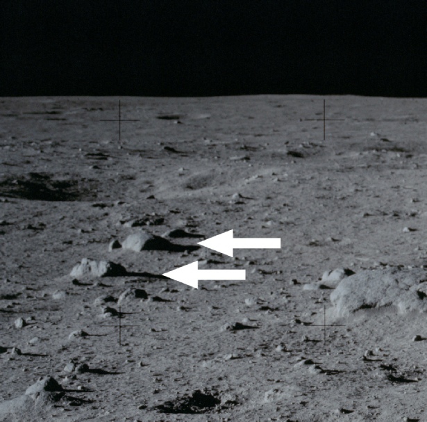
In the images below I’ve taken a frame of the 16mm footage and compared it with the LRO view, using arrows as usual to identify the same rocks in both. The LRO and OHRC views have been rotated 90 degrees to match the direction of travel.
So, having just picked out a few rocks from the many available the ones you can see in the landing footage are an exact match for the LRO and OHRC images, as are the numerous small craters next to which they lie. Can we see those same features in the best available LO shot? In a word: no. Not one. You can barely even make out all the craters. Armstrong’s description of a boulder field is spot on, and the reason it surprised them is because it wasn’t there on their maps and photographs. The 16mm footage picks out it though, and the modern images (particularly India’s) confirm it.
Next, the view from the ground.
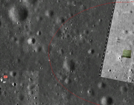
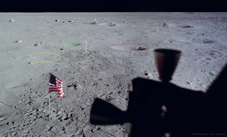
The image below is a composite consisting of images AS11-
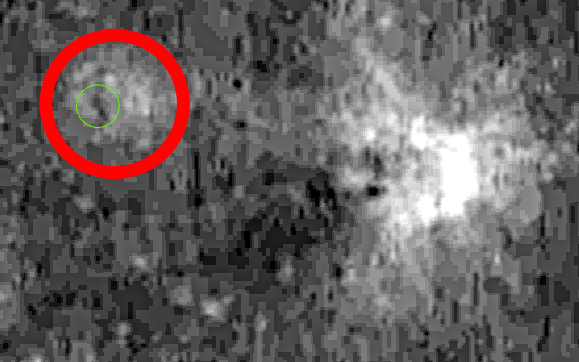
The crater on the right is West, and the red circle covers the entire area of operations of the Apollo 11 EVA. The smaller green circle is centred on the LM, and covers the disturbed ground around it.
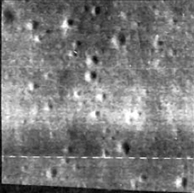
There is, arguably, a difference in shading the corresponds to the activity shown on the LRO images, but it could also be a product of natural variation. The reason it’s not so obvious is that for the contrast to show up there needs to be surface disturbance, and there is simply less of it in this mission.
Here’s a close up -
I’ve made a nice video about Little West crater, which you can see here.
One thing I perhaps could have included in the video is that you can see Little West crater in the distance in some photos, such as AS11-
These two photos, together with the panorama above, can be used to refute a totally stupid claim made by a particularly
Unpleasant moron polluting youtube by the name of expattaffy1. Taffy is a prize idiot, the living personification of the Dunning-
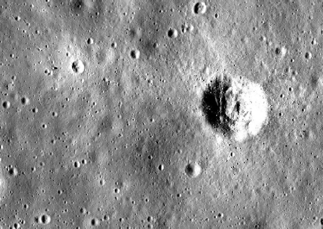
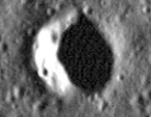
The image directly above, for example, shows a very obvious raised lip on the far wall as it rises above the distant horizon. Above that, you can tell that there is a difference between the edge of the crater and the ground immediately beyond it. In the panorama, the ground very obviously slopes downwards away from the crater rim.
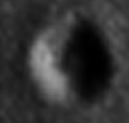
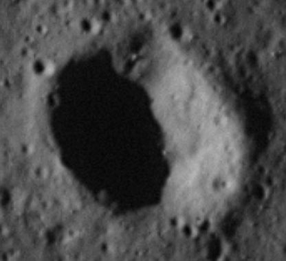
We can demonstrate this even more clearly by looking at a photograph of the crater when the sun is low in the lunar sky.
On the western side you can see that outside the crater there is a zone of shadow, whereas on the eastern side there is a lighter area. The reason for this is because the ground is elevated at the crater rim in comparison to the ground away from it. The OHRC also shows shadowing from a raised rim. Even the lunar orbiter image shows it (below right).
There is no point re-
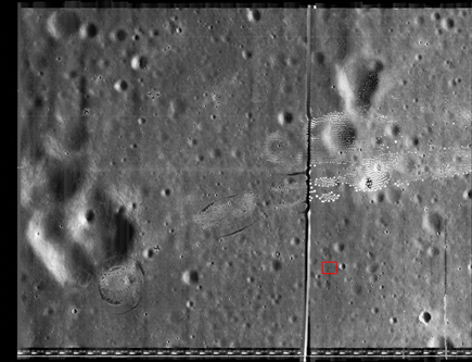
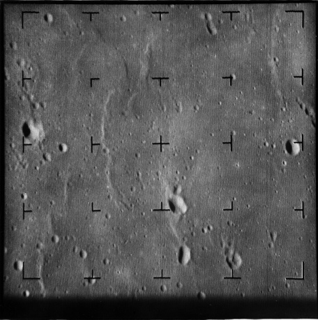
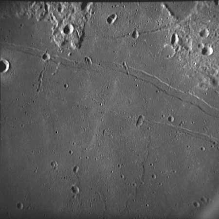
The best quality image from the lunar orbiter is frame 5076, which was taken by Orbiter V, and a high resolution section of that is shown below with the landing site marked. The frame can be found here, where there is also a link to a 17Mb TIFF image of the high resolution image.
The width of the photograph is approximately 13Km across, and the Apollo 11 landing area is roughly in the area marked by the red square.
It doesn’t look so three legged now does it? Despite this release, and the fact that many other places besides this site publicise it and use the images, hoax promoters still need to maintain their grift, using the older low resolution versions as their mascot.
You’ll even get Jarrah still insisting it’s three legged, despite the allegedly missing leg actually casting a shadow -
Well, let’s see -
The literature tell us that Lunar Orbiter 2 images were used, and some conspiracy lovers like to imagine that this proves something, namely that it must have been where they filmed Apollo 11 and all that stuff. We’ll ignore the fact that there were several other missions and that people might have spotted the same craters being used over and over.
The question is, which Orbiter views did they use and which part of those images did the USGS emulate?
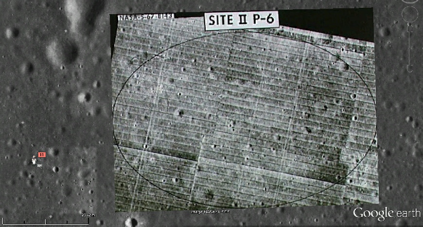
Well, we know from the literature that they were interested in potential landing site II-
Here are the sections of Lunar Orbiter 2 image that they reproduced, the one on the right being a later addition to the Cinder Lakes site.
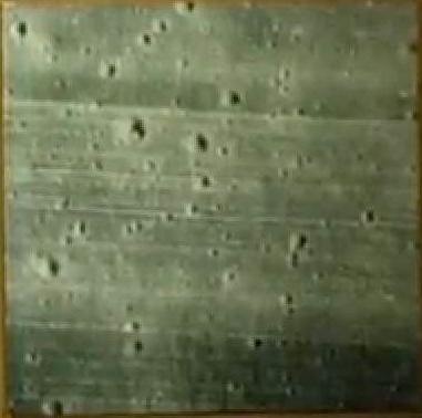
So -
Time for a little logic, combined with guesswork. We know it is an Orbiter 2 image, and it must be a fairly high resolution image to get the level of detail shown. The high resolution images that cover the ellipse are 2084 H1 and H2, and 2085 H1 and H2. It seems reasonable to start looking for the two areas near the centre of the ellipse, and this means we are mainly looking at 2085 H2.
This turned out to be good guess, and you can see where both of the crater fields come from in the image below, firstly in relation to each other (left) and secondly in relation to Apollo 11 (right).
Turns out that far from replicating Tranquility Base, these areas were actually 7 km from it!
Oh, and the Apollo 11 crew never went there! There is no documentation to show that any of them ever visited Cinder Lakes prior to the mission.

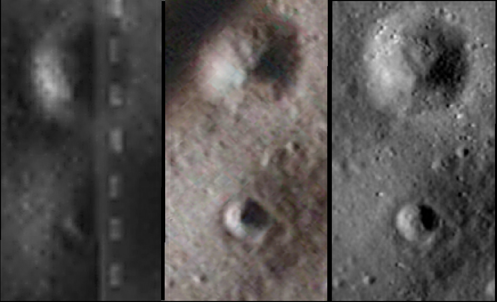
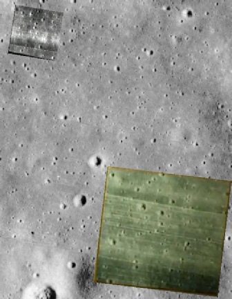
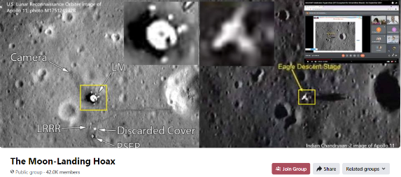
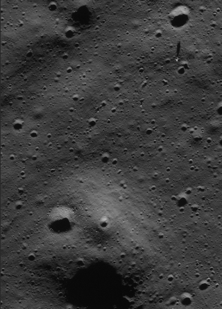
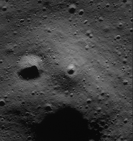
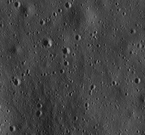
Before looking at modern images of Tranquility Base, it’s worth looking at an additional resource for the site: India’s Chandrayaan-

The OHRC instrument footprint (derived from the Chandrayaan-
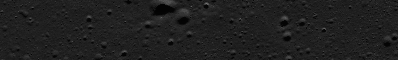
Below is the actual image, rotated anti-
India’s data release schedule is painfully slow, and the first hint that they had imaged Apollo 11 came in this presentation showcasing India’s space research in general.
The release of this image into the wild caused quite a stir, particularly amongst the hoaxtard reality deniers, who immediately latched on to the appearance of the lander, seeing only three legs instead of four.
Jarrah White has an article at aulis (google it) where he decries the poor image quality (we already know it’s a screenshot from a video), hinting at data contamination (ooh, it might have come via some NASA facility or other) and questioning when the full data will be released (my reading is that India is releasing them in chronological order -
The claim that NASA had anything to do with the images is easy to discount. The OHRC manual describes that the image file names include the station used to download the data:
Apollo 11’s OHRC files have ‘d18’ in the name, eg: “ch2_ohr_ncp_20210402T0546284043_d_img_d18”, showing that they were downloaded in Bangalore by India’s own Deep Space Network facilities (something that the deniers also claim they don’t have!). One youtuber insists that “other stations” could have relayed “packets” of data, meaning (I guess) that NASA could have sneaked some data in there, this page describes how Bangalore is the primary receiver of data. It’s bare assertion, he has no evidence to show data were interfered with in any way. In reality, the OHRC was imaged at 05:46 on 02/04/21 (orbit 7150) and downloaded 16 hours later (orbit 7158), which would put India in shot, not the USA (see right).
Jarrah also uses lunar orbiter images to try and prove that Apollo just used the data from them to make their alleged moon sets. He fails to point out the lack of fine detail in the LO images visible in modern photographs.
He insists that the Apollo Mission Report says that Lunar Orbiter V imaged the Apollo 11 site at 1m resolution, but fails to provide the exact reference for that, and nor can he explain how features less than 1m across are accurately seen in Apollo images. He doesn’t seem to understand that a camera being capable of that resolution, and producing an image actually being that resolution are different things. He also claims that the LO images used here are poorer quality than the actual ones form which maps were drawn. Naturally, he hasn’t seen those -
It’s almost as if they were trying to poison the well in advance and make sure they have their get out clauses ready.


He does at least think it’s a genuine image of the landing site:
But it’s quite clear that he’s having to make the conspiracy scenario ever more convoluted in order for it to work. Presumably the ‘fake craft’ was also capable of sending out little robots to install the various bits of equipment that we know is there (and can see in the Chandrayaan-
His argument is that the Chandrayaan-
As we’ll see shortly, it’s also down to the quality of the image from which you get your screen shots.
The lighting aspect is confirmed by the Apollo 11 LRO image taken under similar lighting conditions, as seen in M117338434RC, taken from the Apollo 11 ‘flipbook’ page:
Poor cry-
Let’s look at how the inverted image compares with the Chandrayaan version, which I have inverted for comparison.
Seriously, what’s your problem?
It’s an Apollo lander photographed under similar lighting conditions. All you proved in your ‘analysis’ is that they look the same under those conditions.
Here’s the thing Jarrah: it doesn’t matter where the data come from. It doesn’t matter when they are released or by whom. Neither ISRO nor any other space agency has to jump to your tune and conform to your arbitrary standards of acceptability. You are not important to them, they don’t have to appease you.
The fact is that Chandrayaan’s image shows Apollo hardware. Prove it doesn’t. The fact is that (as we’ll see shortly) the details in even the poor quality version of the OHRC data shows features that exactly match Apollo 11 images, details not visible in LO photographs.
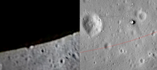
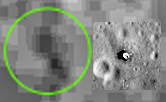
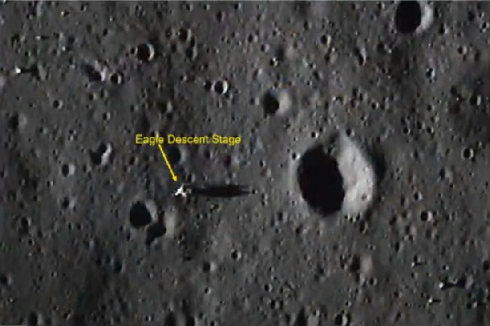
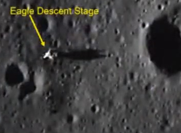
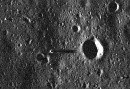
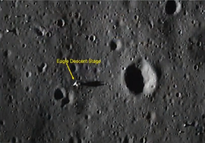
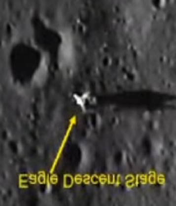
The worst fears of the window-
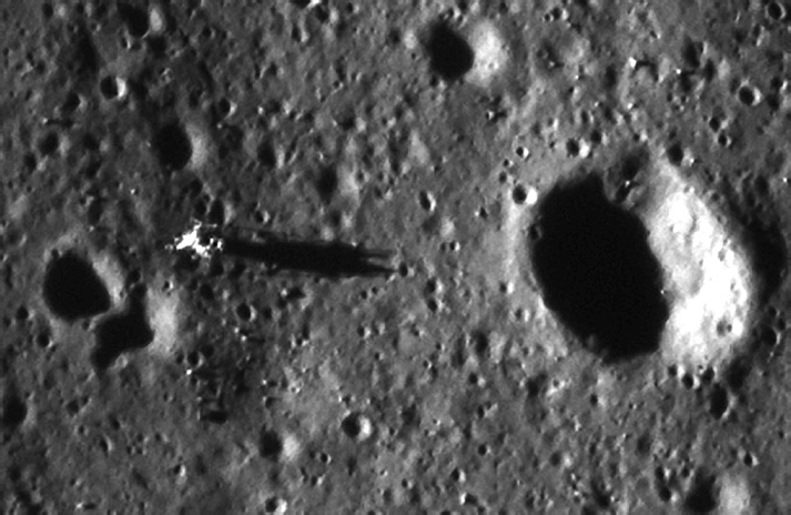
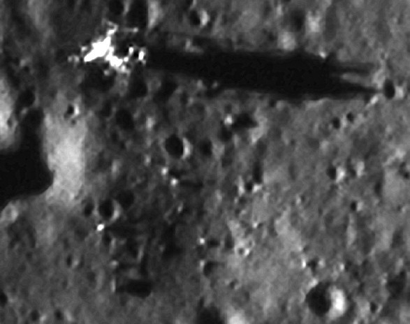
They aren’t the best quality, but we still have enough detail to show the path to the TV camera, a hint of a trail to Little West, and the LM itself in the more well lit image. The other photo clearly shows the long LM shadow stretching over Little West crater. The large white flare is interesting, and could be light reflecting off the LRRR mirrors, which is in roughly that spot and angled towards the sun. South Korea’s experts certainly draw that conclusion.
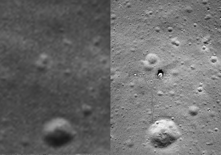
Having given the area some context and seen what images are available, let’s now zoom right in to the landing site. The centre shows a section of one of the LRO images enhanced by GoneToPlaid. If you doubt its veracity you are welcome to take it up with him, or the LRO’s operators. I chose one with the highest resolutions available, and by superimposing the Orbiter photograph was able to identify the same areas. The image on the left is the Orbiter, the one on the right is Chandrayaan-
So, what about elsewhere on the landing site? During their brief stop they went over to Little West crater, and while they were there they took several photographs that make up this panorama. I’ve cropped the image to make it fit on this page a little better.
So there we have it.
Modern lunar probes confirming details shown in Apollo photos not known about before missions.
Prove me wrong.
The view from China
In April 2018 China released much higher resolution versions of its images from Chang’e-
It’s a little trickier for Apollo 11 given the small size and relatively featureless nature of the landscape, but here is China’s view (left) compared with that of the LRO.
While the others compare those taken on the surface:
Jason used this source to work out how to get the image from the OHRC. You can too, if you want to. The data are not secret, anyone can process the raw images and see for themselves.
Also joining in the fun is South Korea’s Danuri probe. Primarily intended to image deeply shadowed craters at the lunar south pole, it also has a terrain imaging camera. The raw data for publicly released images are here. There are two images, one taken 30/03/23, the other on 10/05/23 under much less illumination. I’ve used my own processing of the raw images.


Apollo 11
Before looking at the photographs available of the Apollo 11 landing site, it’s worth looking at how the original purpose of the Lunar Orbiter images, to detect a suitable landing site, were put to use.
One of the uses is described in this article, which details how the lunar orbiter images were used to build a 1:2000 scale model of one of the proposed landing sites for use in a lunar module training simulator. Measuring 16 feet by 20, it represented an area roughly 5.3 miles wide by 8.3 miles long. It was eventually ready in February 1969. It references ‘Site 3’ as one produced for Apollo 11, but it isn’t clear whether this is the one they actually landed at!
One such use happened at a place called Cinder Lakes, where the USGS spent a lot of time and effort recreating a 1:1 scale replica of part of the Sea of Tranquility in which astronauts could practise their skills.
There are some interesting documents showing how they created the fields here and here, and a video here. Here’s what it looked like (the image below left compares the cinder lakes site with the actual LO image):


As you can see above left, the first use of the images was in June 2021, 2 months after the images were taken. The lower resolution ones that causes our conspiratard friends so much trouble were broadcast on September 2021 (above right).
Meanwhile, unperturbed by the collective stupid’s false conclusions, Chandrayaan-


It’s the grift that keeps on grifting: keep lying to your deluded followers and maintain that engagement.
As also explained on my Apollo 12 page, Jarrah’s argument (and the even more ridiculous one that ISRO were bullied into adding a ‘proper’ LM into the images by NASA) really falls apart when you realise one simple fact: the high resolution OHRC images were released three months before the ones about which he’s frothing at the mouth -


Three legs?
No. You can easily see where all four legs are, and the shadows cast by the leg he thinks is missing (yellow arrows).

I’m also not the only person who has been able to make these comparisons. In this excellent Twitter thread, user ‘Jason Major’ makes his own comparisons.
These two look at footage taken on the descent:


I’ve rotated the Apollo 11 view to match the LRO north. You can find the area at roughly these coordinates: 0.74. 21.62
The red square is just a random point of interest -


And here’s the same approximate area of the wide scale view from Lunar Orbiter.
There is precisely fuck all detail there.
The ‘detectives’ can claim it’s model all they like, they have no explanation as to how they came up with the alleged model: a model that had details in it that they did not know about before getting there.

That 7km distance means tha the craters in the photo were barely visibly from their position in the LM above them. Here’s the view in Google Earth compared with the view from the LM -
The large crater towards the bottom left of the video still is just above the centre of the Google moon view. Just to show the differences in actual terrain, the two Lunar Orbiter location used to create the training area are shown below.
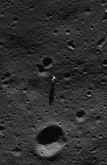
A lot of people mistake the pointy bits of the LM shadow as being an intact ascent module.
They aren’t -