The blue area is compared with a high resolution GoneToPlaid LRO image below, which we will use for the moment as it shows the craters around the LM in high detail.
As with previous missions, superficially the LO3 photograph contains a very similar amount of detail, but there is a data error running across the centre of the view where two strips have been joined that obscures a lot of the information they needed. It’s also obvious that the LRO view shows a lot of rocks and small craters that are not seen in the LO3 photograph.
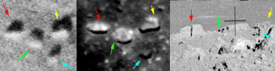
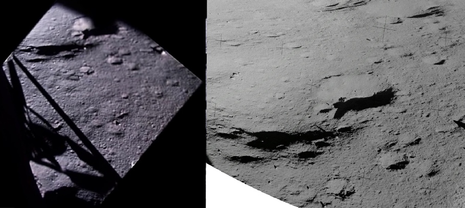
Can we be sure about that? Well, let’s start at the beginning, as this is a very good place to start, and look at the 16mm footage taken as they approach the landing area. The centre of the image below shows a still taken shortly before landing, while to the right is the LO3 view of the same scene, and the LRO to the left. Both probe views have been rotated to match the view of the camera.
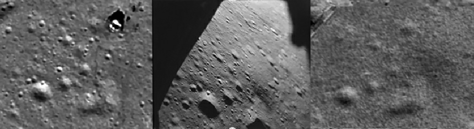
The main features in the still, the craters forming a ‘7’, are evident in both probe views, as are some of the larger craters around them. What are not visible in the LO3 view are the many smaller craters. The larger crater at the bottom of the ‘7’, for example, has a small crater on its lip, but this is only shown in the LRO view. The central crater along the top of the ‘7’ is barely visible in the LO3 still, let alone the two smaller craters on its lip.
A few moments later we have a still showing the scene just before landing as the LM begins to pick up dust. As before, the LRO is on the left, the LO3 on the right.
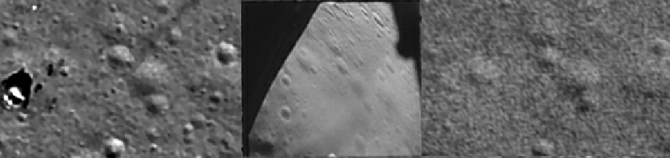
The LO3 craters have all but disappeared with only blurred views of the larger craters. The two vertically aligned craters near the left edge of the 16mm still can be seen clearly on the LRO, with one of them having the shadow of a piece of equipment in it (the High Gain Antenna). On the LO3 view they are hardly visible at all. The crater to the right of the LM with two smaller craters on opposite sides of its rim is eay to make out in LRO and 16mm still, but not on the LO3 view. The smaller craters in the distance in the still are also discernible in the LRO photo, and nowhere to be seen in the LO3.
We can have one more look at the descent footage as we get closer to the ground, this time at one of the last clear shots we get before the dust takes over completely. There’s no point using an LO3 shot in this one.
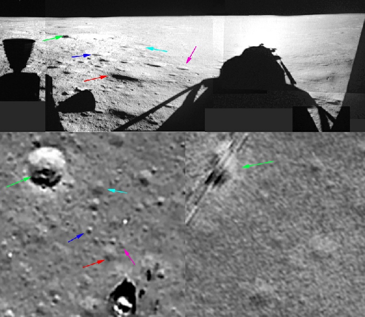
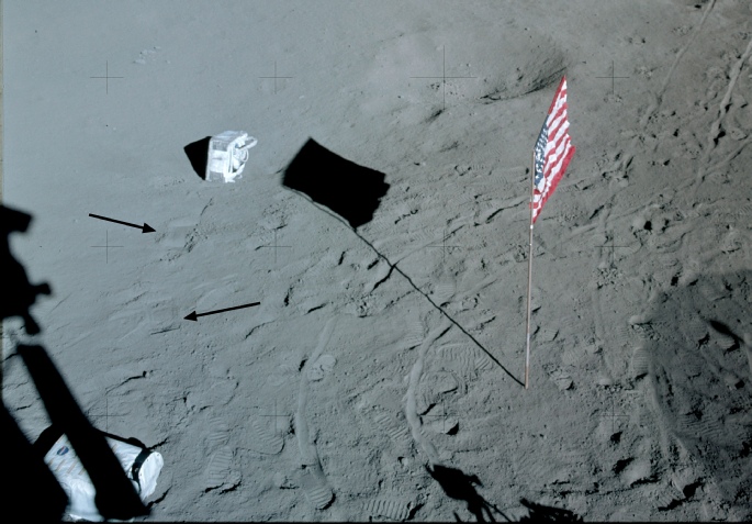
In the LRO view, the flag and antenna shadows are to the right of the LM, which means the the Commander’s view is looking left of vertical towards the top of the image. The key to identifying whether we are looking at the same view comes in the form of the ‘L’ shaped line of craters in the centre of the LRO image (see the magenta, blue and sky blue arrows), immediately below which is an ill-
Can we see the same features in the LO3 view? No, we most certainly can’t. Not only is the view out of the window consistent with the orientation of the LM as determined by the flag and Modular Equipment Transporter (MET) shadows, the view itself is consistent with LRO’s photo of what should be there, and these features could not have been placed using LO3 images.
What about the LM Pilot’s view -
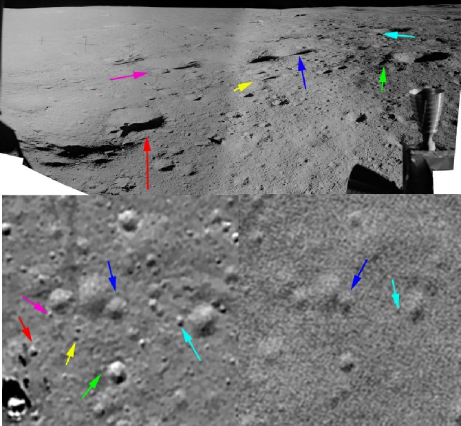
The craters in the bottom left of the Apollo image are the same ones that were picked out during the landing video, and shows a shallow small crater to the left of a larger central shallow crater, with a deeper and more pronounced crater to the right, and this is the one that is most clearly picked out by the LRO. But hardly noticeable in the LO3 view. In the background is the complex of 4 large conjoined craters, with the left-
The ALSJ has several LRO images that have been annotated and researched to identify the locations of sampling points and panoramic shots during the mission. There is no point in going over the same ground as they cover there. Feel free to browse through them, and take care to compare them with the many pre-
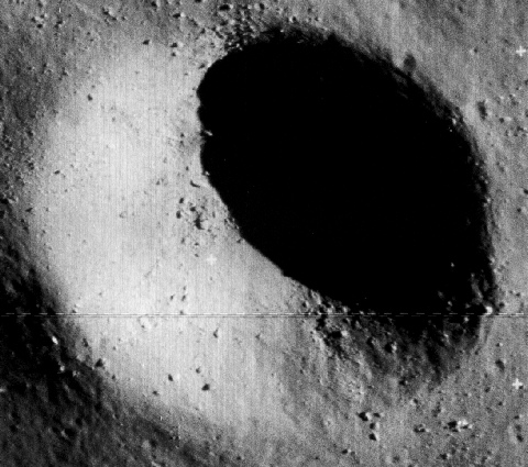
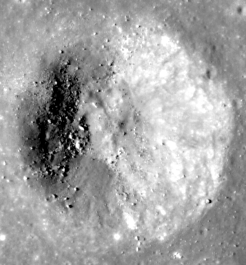
In some areas there is a good correspondence, and perhaps even equivalent quality, between LRO and LO3. The LOIRP’s recovered version of the photograph has been examined by them (see here), and in the interest of fairness it is perhaps worth looking at their findings. They looked specifically at Cone Crater, and more specifically still at some of the larger rocks at the rim of the crater. The image below shows the crater viewed from LO3 (left) and LRO (right).
Let’s try and talk around the photographs and see how they compare.
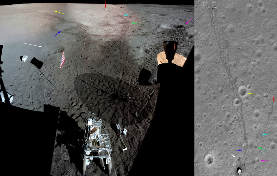
You’ll of course recognise the PLSS and the crater identified by the white arrow from the descent footage analysed earlier.
Heading right from the MET there is a broad path that ends in a decent sized crater (magenta arrow, where the TV camera is), which is pretty obvious in both. Heading towards the horizon in the Apollo photograph the footpaths diverge around the left-
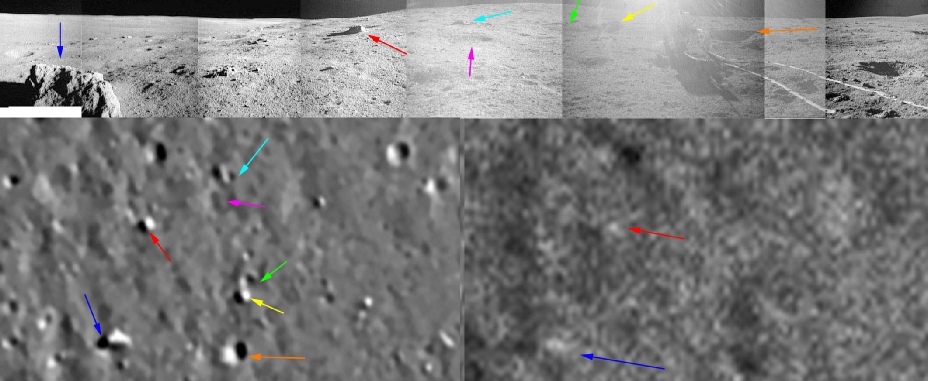
Another path heads off around the right hand edge of the triplet of dimples and towards a white object (red arrow) almost half way up the right edge of the LRO image, as the path heads towards this object it separates around a small crater. The white object is ‘Turtle Rock’, which is present in the LRO view but not LO3. There is a panorama taken next to this rock (see here for the full version, only part of it is used below), and we can briefly return to the LRO for a quick look:
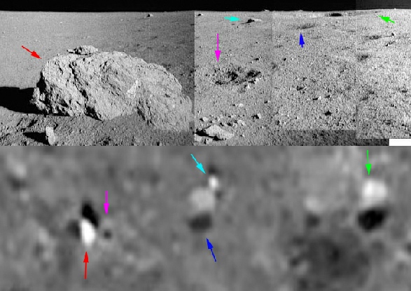
From left to right we have Turtle Rock (red arrow) , next to which is a small crater (magenta arrow). In the centre of the LRO view is a shallow crater (blue arrow), at the back of which is a small protruding rock (sky blue arrow), and at the far right is a larger shallow crater with a smaller deeper crater on the edge of it (green arrow). Can we see this in the Apollo view? Of course we can. Can we see these features in the LO3 view? Go take a look, only the larger crater with its smaller crater on the edge is visible.
We digress. The longest path heads towards the ALSEP scientific equipment, as it does so it threads through some larger shallow craters that can be found on a slight ridge in the Apollo image. At the ALSEP itself the various footpaths pass by a large shallow depression, and again this can be seen on the Apollo view if you zoom into it. Only the larger craters near the ALSEP are visible in the LO3 photograph.
The paths can be seen most dramatically in the take off footage recorded by the Ascent Module.
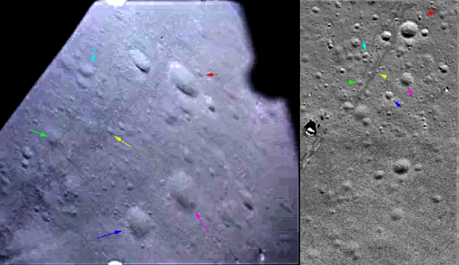
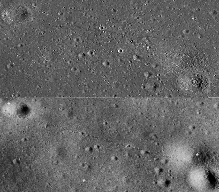
For our final look, we can examine the images taken from the elevated position of the LM (which certainly makes life easier when trying to pick out craters after the EVAs), and see how the patterns recorded in the photographs match up with the LRO photographs. We’ll have a change of LRO image to one that shows the trails and equipment a little more clearly (this one). There is a panorama at the ALSJ that shows a good view, available here, and this is shown below with the LRO view. I have adjusted the levels in the image to improve the contrast between the darker trails and the lighter undisturbed soil. I have made no other alteration.
The above shows very nicely how much detail the recovered LO3 images show, but does this one show enough to reproduce the scenes in the Apollo photographs? In the bottom right of both images is a rock formation called Saddle rock, named after its shape. It’s the bright white feature in the LRO image at around 5 o’clock.
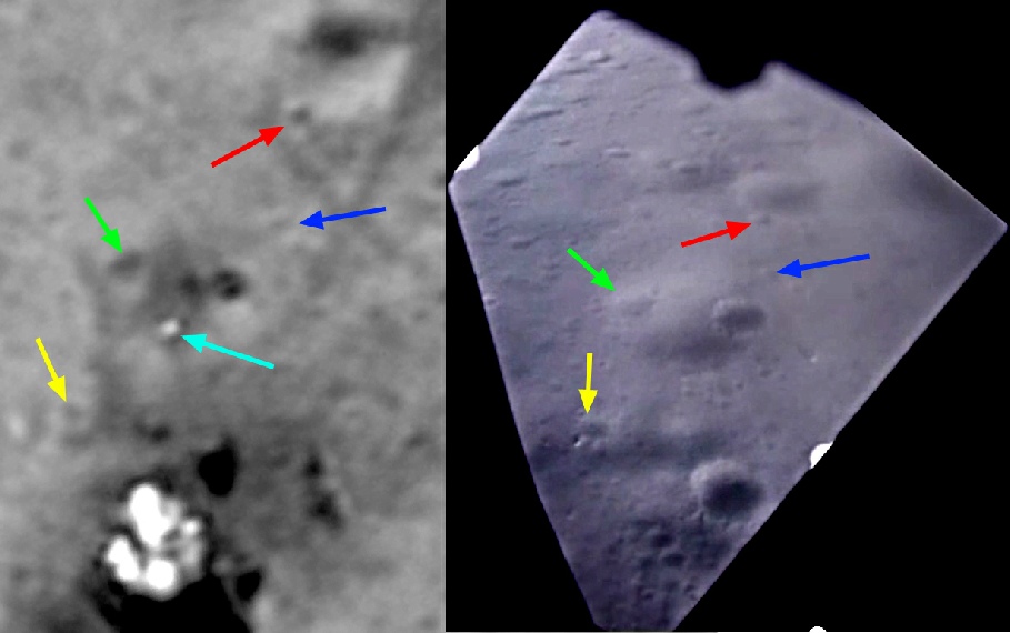
The image below shows the view from Station C on the crew’s 2nd EVA that I composed from images AS14-
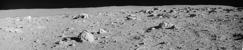
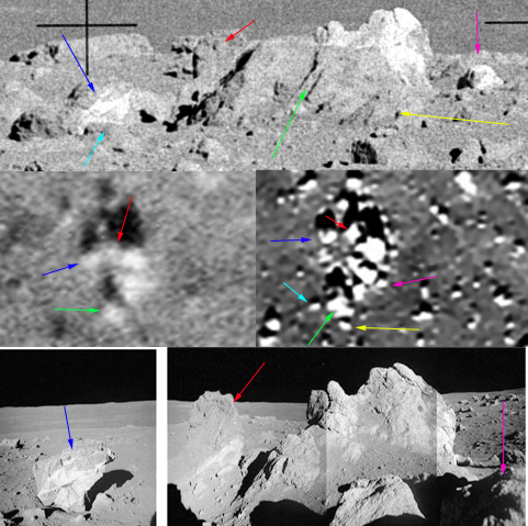
First off, let’s have a look at the left hand edge of the image. We can see Saddle Rock, and to the left of that, obviously further away, are some much broader flatter rocks. I’ve isolated this area and it is shown below.
They key area here is a feature that appears in the Apollo view: a large and very obvious vertical crack in the rock identified by the red arrow. This can be made out in the LRO image (centre) but not in the LO3 one. Detailed features can also be made out on the rock identified by the green arrow, specifically the sculpting on the left edge which again is not clear at all on the LO3 view. Good as it is, the LO3 image shows the locations and relative dimensions of the 4 rocks, but not the detail of them. It is even difficult to determine precise shapes, whereas it is obvious from the LRO that they are flat, just as they are in the Apollo photograph. The LRO also shows the numerous much smaller rocks scattered around the larger ones, but in all honesty it is difficult to identify them on the Apollo view, thanks to the difference in perspective.
Now let’s look at the Saddle rock area. In the above panorama it’s over on the left (to the west). We can use a different and much more detailed view of the area done by GoneToPlaid, with a resolution of up to 0.25m per pixel -
As with the previous image, the LRO view contains much more detail that the LO3 one, and allows us to be reasonably confident that we are picking out the correct rocks in the Apollo viewpoints. Our main enemy here is perspective, which makes the distances between rocks deceptive.
The blue arrow here has been used to identify what became known as Contact Rock. We can definitely be certain we have picked it out correctly in the two Apollo images by the patterning on it, as shown below.
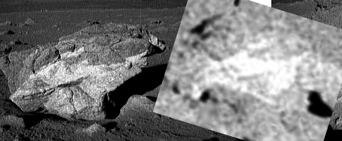
Because we know the orientation of this rock in relation to Saddle Rock, it is relatively straightforward to pick out the others in the LRO photograph.
Can we be as certain in the LRO image? The answer has to be no, which is why some arrows have been omitted. The general outline and distribution is there, but the fine details are not. The LRO, for example, shows enough detail to allow the location of the cracks picked out by the green arrow to be identified.
We can broaden out our perspective now to try and identify some of the other features.
Saddle rock is in the top right of the Apollo picture (top), and as before, the LO3 photograph reveals the locations of the major boulders, but for the finer details we need to look at the LRO photograph. What should stand out from the arrows used to highlight those major boulders is that the much smaller ones can also be picked out.
We can even make out, on for example the boulder in the foreground highlighted by the blue arrow, cracks and other features that allow them to be identified correctly.
While the crater was their intended destination, confusion over topography and concerns over time and the astronaut’s oxygen use during the strenuous uphill walk meant that they never actually made it to the crater proper. Discussions with the LOIRP on their Facebook page reveal that one member of Mission Control told them that if they had had a map with the quality of the recovered image, they believed they would have found the crater rim! I think that says something about the differences between the modern reworking of the data and the originals.
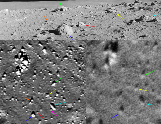
We can also find some areas away from Cone crater where this LRO image reveals fine detail not visible on the LO3 one. The image below, for example, shows a crop of the pan taken at station B2. Because the direction to cone crater has been worked out, we can orient the photograph, and because we know where it was taken we can look for features that match. I believe I have identified the correct rocks and craters in the LRO view, features which are, for the most part, not visible in the LRO photograph.
Another one to look at before we look at the imprints the astronauts left behind is from station B on the way to Cone crater. In the ALSJ, the caption for this panorama describes the difficulties in finding your location when there are so few landmarks, and as the LO3 image (below right) shows, the maps they had did not show the details they needed to pinpoint their exact location.
The LRO image (below left), on the other hand, is good at picking out small rocks, and once again there is an excellent match with those found in the Apollo images.
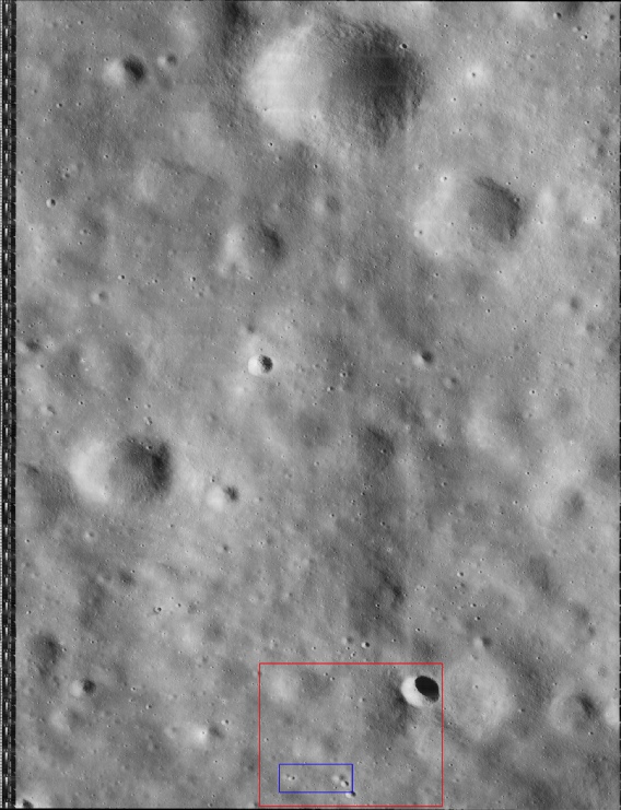
The best Lunar Orbiter image for Apollo 14 is again from LO3, image 133_h2 and can be found on this page. The LOIRP team have rescanned the image as a 700Mb TIF, available here, and this larger TIF is the one used as the basis for analysis here, so as to ensure the best possible level of detail in the comparisons. Different LRO images will be used depending on which shows the best features under examination.
The image below shows a lower resolution version of Apollo 14’s area of operations marked in red. As one of their EVAs involved quite a walk the area is quite large, and the inner are shows the area around the LM (in blue).
To the right of the 16mm still, the top half of the vertical views shows the LRO’s perspective on things, the bottom the LO3.
There are two things to be looking out for here. Firstly, the ascent footage (which, it must be emphasised, starts from the ground and continues uninterrupted for quite some time) shows details of craters that can not be seen in the LO3 photograph. Yes, the larger craters are there, but the smaller ones and those shallower ones that have less shadowing are not evident. Even the large bright Turtle Rock can’t be seen on the LRO view.
Secondly, there are the footpaths themselves, which match in every detail, for example the sharp ‘dog-
You either have to admit that the details are exact because the images were taken where they have always claimed to have been taken: on the Moon, or you have to start making ridiculous accusations about the LRO images being faked to match the video record. The fakery would have to extend way beyond just marking out footpaths and hardware, but also to adding craters, dimples and rocks that the Apollo team would have had no idea about unless they had actually seen them with their own eyes.
Before we leave Apollo 14 it’s worth having a quick look at another view of the landing site, that provided by India’s Chandrayaan probe on orbit 757 on 01/10/09.
By registering at their website, it is possible to request the raw image files and then use their own software to zoom in on the details.
By overlaying a low quality version of this orbit’s image on Google Moon I was able to identify the area covering Apollo 14’s landing site and extract the relevant part of the raw image.
Once that had been done I was able to perform the same kind of adjustments that I have to every image I use (level adjustment, sharpening and so on) and the result showing the entire landing site is shown below.
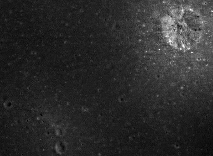
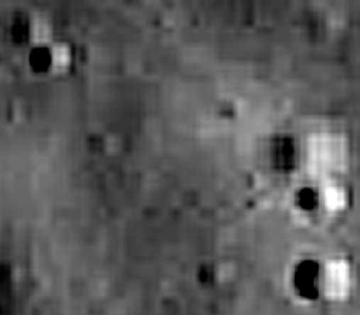
If you look towards the bottom left of the image you can see a dark smudge and a darker horizontal line. Not clear? Let’s zoom in to the same sort of view I used earlier.
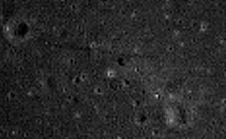
And just so we’re absolutely clear what we’re looking at here’s a gif overlaying the LO, LRO and Chandrayaan views of the site. On the right is a view taken by the second Chandrayaan probe, again confirming human activity.
What I believe we have here is confirmation from two Chandrayaans of Apollo 14’s activities, which represents 3rd party evidence uncovered by independent research (ie me!). Anyone who wants to look at the data to check I haven’t fiddled this is welcome to do so. All the evidence is out there for you to look at and work on just as I have. It’s not 100% conclusive, but it is a hell of a coincidence that we have shadows and marks exactly where Apollo 14’s activities took place.
While you’re at it you might also want to look at Cone crater as viewed by Chandrayaan-
Or the Indians are in on it as well.
As well as the Indians the Japanese are also in cahoots -
Aaah now it becomes clear -
In short, despite using a digitally remastered version of the original LO3 image, it does not show anything like the same level of detail as the LRO view of the same scene, and the details in the LRO photograph coincide exactly with those shown in the 16mm still.
OK, we landed, what can we see out of the window, and more to the point, can we see the same things from lunar orbit?
One of the first sets of photographs were taken out of the two windows of the LM. These two windows are positioned so that they are either side of the strut that holds the ladder. On Apollo 14, the flag was positioned close to that strut, and its shadow has been identified on LRO images near to other equipment. This should allow us to pick out the craters that can be seen from the LM window.
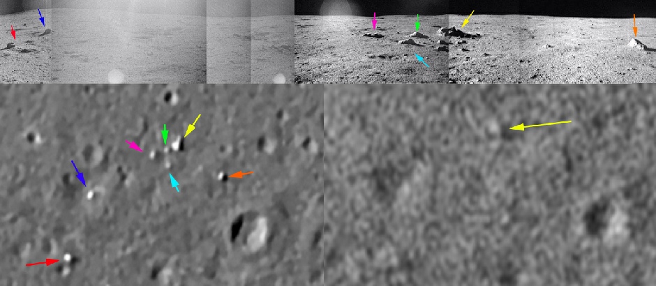
The first one examined here is that from the Commander’s window (available here), to the left of the hatch, shown below with the LRO (left) and LO3 (right) views of the same scene.
I’ve put arrows on this one to help with the increasing fuzziness of the LRO image, but even without them it should be obvious which craters are which, and that small details can be made out here that are just not present in the LO3 photographs.
Hang on though, what’s that feature identified by the light blue arrow at the bottom of the crater that looks like Mickey Mouse? It isn’t there in the descent footage, so what is it?
Well. Let’s first establish what we’re looking at. Here’s a frame after the dust had settled compared with a pre-
What this shows is that the crater in the centre of the LM photo and the top of the 16mm frame is the crater in the centre of the descent footage -
The feature identified by the light blue arrow isn’t in either of these two, so we need to move on to a post-
In both views the LM shadow can be made out in exactly the same place as the one shown on the LRO, although it is much more prominent in the evening view. The morning view also shows the disturbance created by the astronauts going about their business.


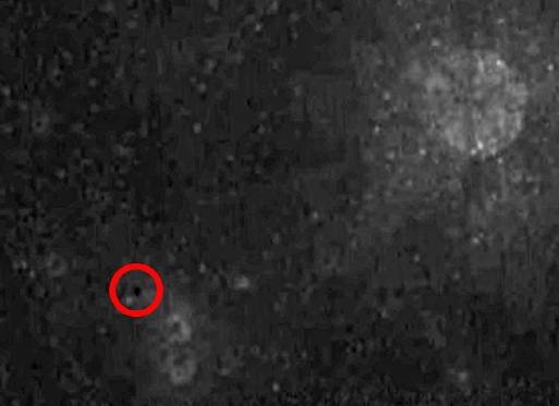
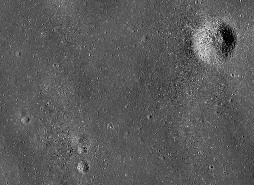
As with the other Chinese images in this series, the red circle identifies the location of the LM, and the equivalent areas zoomed in are shown below.
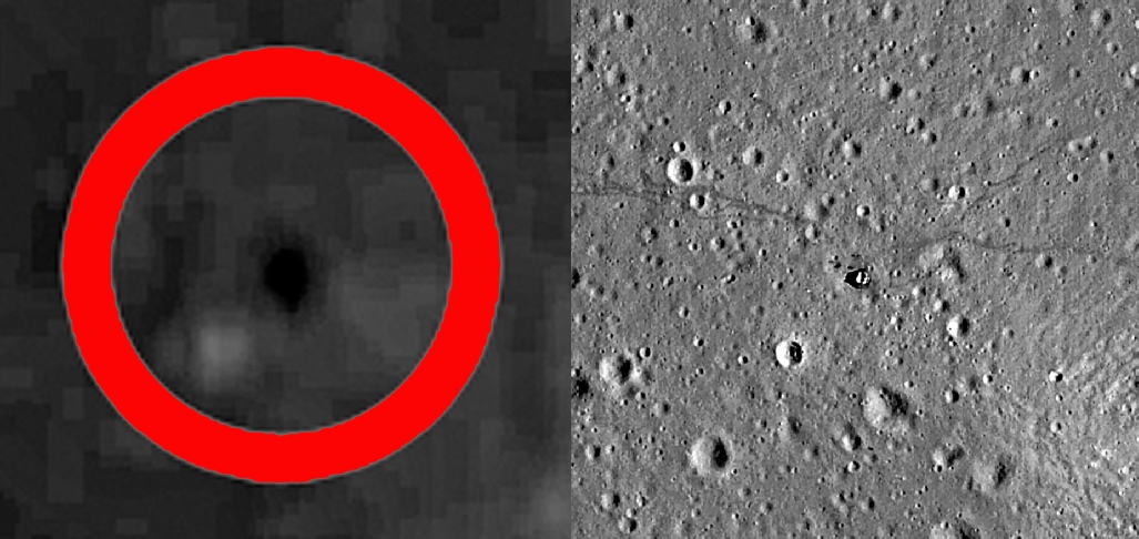
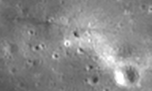
It’s interesting to note that the 2 EVAs have produced a much wider, and more intense, darker area compared with Apollo 12, and this again is indicative of activity rather than hardware. Activity that is much more difficult for conspiracy idiots to explain.
And because some people just don’t pay attention, like the Apollo 12 views shown by Chang’e-
CE2_BMYK_CCD-
CE2_BMYK_CCD-
The view from China
In April 2018 China released much higher resolution versions of its images from Chang’e-
 Lunokhod 2

So, India, China, South Korea and Japan all confirm the presence of a lunar module and human activity on the moon as well as the USA’s LRO probe.
Watch out for goalposts being moved at a hoaxtard website near you any time soon.

Cone crater is top right, and and North crater, triplet and South Apollo crater are below and to the right of the circled landing site.
They do even better with their LUTI instrument, capturing not just the LM and the trail towards the ALSEP, but the path to cone crater in June 2023:

They had another go a months later (July 2023), showing details exactly matching the trails shown in the Apollo record and LRO views

Apollo 14
Apollo 14 provides us with some nice new information to play with, as the video footage available includes not only the landing but the take off by the ascent module, which reveals the evidence of human activity as it heads for its rendezvous with the Command and Service Module.
To some extent a little of the work attempted here has already been done by the Lunar Orbiter Image Recovery Project, locating a particular rock near Cone Crater (see here).
The site was also modelled for training purposes, although it was originally intended for Apollo 14. This article describes how it was produced, and the model from that article is shown below.

Chandrayaan-


And a couple more in October 2023.


This one from 04/12/23 clearly shows the path to cone crater, as well as the very obvious lunar module.

There it is. Clearly visible: the darkened ground surrounding the Apollo 14 lunar module.
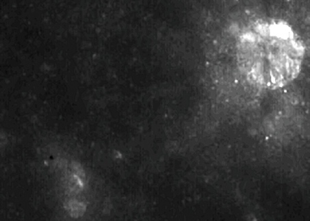
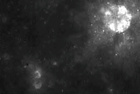
We can add South Korea to the list. Their Shadowcam instrument has been imaging Apollo sites under Earthshine conditions, and this image definitely shows a dark spot around the lunar module.


Once you’ve done the usual processing and location finding, here’s what you get -