There is yet another strand of conspiracy theory codswallop that says that the details in the Apollo images of the lunar surface were obtained by earlier lunar probes in the Lunar Orbiter series, or some other unnamed and mysterious source, in order to construct studio sets.
Obviously this does create some problems for the landing deniers, because they have to concede that rocket technology capable of sending things to the Moon and returning a signal did exist long before the the first human orbit of it. Even the Russians had been at it, beating the Americans in a number of areas of lunar exploration, as well as getting a probe to land on Venus.
What will be attempted below is to try and examine details revealed about the landing sites as they are today, and comparing them with what we know was available at the time of the missions.
For more background information on the Lunar Orbiter probes, see here. This site also contains useful information, and is the source of new scans of the orbiter photographs. This document gives a detailed history of the Orbiter programme, while much higher resolution images can be obtained from this USGS site. More detailed information on the imaging and printing processes can be found here and here.
In brief, one of the main aims of the probes was to provide photographic data on the Apollo zone of interest -
While one camera lens took a large scale view, a separate lens zoomed in on much smaller areas. The highest resolutions are claimed to show features just a few feet across. Obviously, argue the conspiracy lovers, this means they must have been capable of providing the detail of the lunar surface needed to generate the photographs taken by Apollo. The lenses and film it used were from previously classified spy cameras developed in the late 1950s. It was deemed unsuitable for actual spy satellite use as it was only visible to ground stations for a short while, and the unencrypted transmissions could be intercepted, so the system was co-
In order to get the photographs to Earth, they were developed inside the Orbiter using an automatic process much like the one that used to be used to print DIY passport photographs from booths in shops, but with fewer ‘wet’ chemicals. The developed image was then scanned, and this scanned information was transmitted back to Earth essentially as a video signal, with modulations in the signal proportionate to the light signal received from the developed negative.
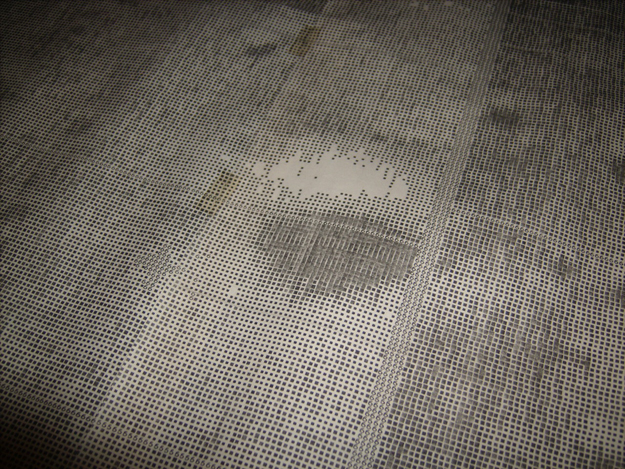
At the Earth end of things, the received images were scanned again on a kinescope and printed out, line by line, on long rolls of paper using different sized square blocks to represent the light level in a specific part of the image. These prints could be quite large, and individual strips up to 25 feet long were used to compile the complete photograph, shot from above in a large building.
This long convoluted process, where an original photograph was transmitted to Earth, re-


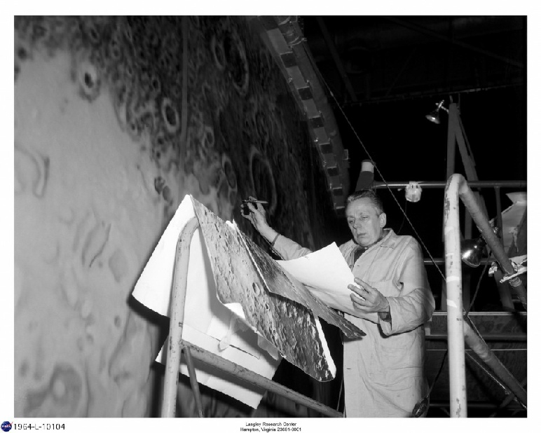
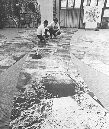
The first photograph below below left shows a NASA technician with a ream of photo printouts used in assembling the lunar orbit simulator, and gives some idea of the size and quality of the printed images, as does the image below right showing orbiter 3 images laid out.
As luck would have it, I am actually in possession of a couple of original large glossy prints of two Orbiter images.
The left one is the so-
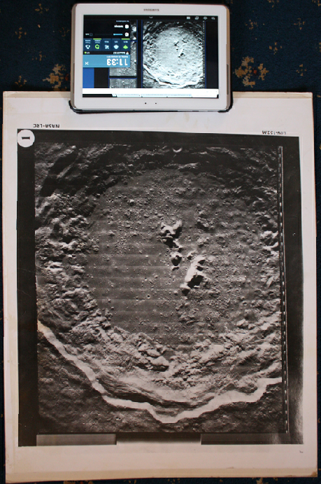
The photograph to the left shows a comparison of a section of the 17Gb RAW TIFF scan of the Tycho image (left) and my own full size glossy (right).
It’s fairly obvious from this comparison that the scanned images are a good representation of the glossy originals available to NASA, although the scan is noticeably sharper. A magnifying glass would have been required to view the same level of detail visible above.
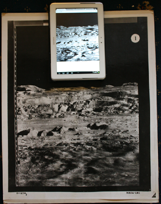
The image shown below left is a close up view of the original glossy image (bottom) compared with a ‘digitally remastered’ view from the same image done by the LOIRP (top).
More detail from the original can be recovered with some digital processing in Photoshop, but obviously this wasn’t available to the Orbiter teams at the time (see below).
It’s fair to say that the scans available on line seem to be a good representation of what was available to the original NASA teams using them to find landing sites, produce simulators for landing rehearsals, and produce maps for the Apollo crews. The quality of those simulations will be dealt with on each mission page where available.
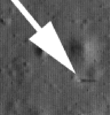
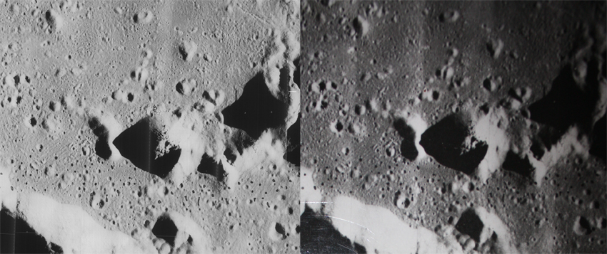
Surveyor 3 will be dealt with under the Apollo 12 section, but here’s a quick view of the probe as viewed from Orbiter 3 (left) and the LRO (right).
This time, the shading in the crater makes it difficult to make out the location of the probe, which has been marked by a small white triangle in the Surveyor report.
We therefore have satellites capable of identifying small surface details, including equipment from unmanned probes.
This feature is something that, as you will see if you care to look at the additional pages linked to below, is repeated in image after image. From altitude, Lunar Orbiter images do a superb job in rendering the lunar surface. From close up they do not reveal the same amount of detail as Apollo video, TV and still images.
Could the Lunar Orbiter images have been used to create sound stages or other models to fake the Apollo landing sites?
In a word no. All it takes is a little research to show this, something which the Apollo Detectives could have used to avoid making utter dicks of themselves yet again.
In this video, they talk about the LOIRP.
They keep describing it as ‘Apollo’ film. It is not. They seem to think it’s the original Apollo 11 telemetry back up tapes. It is not. They also keep describing it as film, with some intercuts of footage of developed film showing the lunar surface (presumably from a LOIRP film, they don’t identify it.), not to mention clips of recently found EVA footage from Apollo 11 put up for auction as if that was somehow connected. It is not. They invite people to tell them that they’re wrong, and to explain why, complaining that people never do.
That’s bullshit, they get told that they’re wrong all the time, and why, they just delete the comments that say so.
So, let’s pick apart their claims. They claim that the tapes were discovered in 2009 in a McDonalds, which they found out by “having a look on Google”. .
Nope.
The tapes were moved to that recently abandoned McDonalds in 2008 after having spent years being stored in a garage. They were scheduled for disposal by NASA, but one employee felt they were too important to lose (and she was correct!). They were never ‘discovered’, they were always known about, it just took a long time to get funding and machinery to recover the data on the tapes. The McDonalds was just a convenient place to do the recovery work.
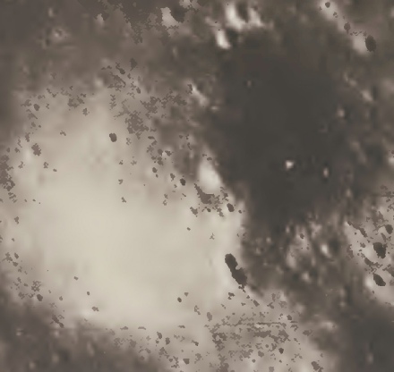
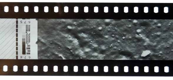
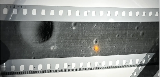
Here’s that (presumably) lunar orbiter film segment, compared with a piece of lunar orbiter film found on a couple of sites (source, source).
It’s difficult to tell from the scanned images available now, some of them re-
The image to the right shows a small section of the type of print-
There are also images from contemporary publications that show the kind of detail available at the time.
One such is the use of Lunar Orbiter 3 images to locate the Surveyor probes on the moon, particularly Surveyor 1 and Surveyor 3, later visited by Apollo 12.
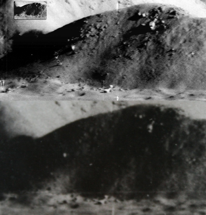
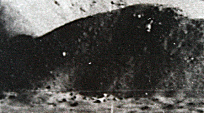
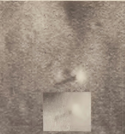
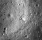
This publication contains a number of references to that process, and the image below shows the Surveyor 1 probe as revealed by the 3rd Lunar Orbiter probe (left) and the modern LRO (right).
The inset shows a mock up of what they ground based photo-
The film strip they’re showing, and implying is from these tapes” is not directly from these tapes, it’s a 35mm reproduction of the original film, as detailed here. You could have a long discussion about whether these tapes contain data or photographs. The original documentation describes how:
“The video signal received on Earth was fed into the ground reconstruction electronics (GRE) where it was converted into an intensity modulated line on the face of a cathode ray tube. This line was used to expose 35-
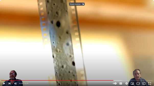
So what he’s holding up isn’t from those tapes, it’s what’s produced from those tapes. The tapes are an analog of the original film from space. It’s not a film you can hold up to the light and interpret. It is, to all intents and purposes, data.
The tapes in the McDonalds are not from Apollo missions, they pre-
This video, and this one, explain more about the project, and just the tiniest amount of actual detective work shows up what dishonest, ill-
Meanwhile, use the links below to see what actual detective work looks like for Apollo surface and orbital photography. There’s also a new section looking at the USSR’s Lunokhod-
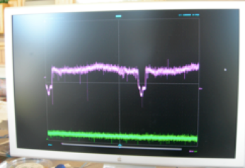
In other words the tape contains a signal that records variations in light intensity transmitted through the film in lunar orbit, which is then used to reproduce what the film looked like on Earth. Here’s the signal being played on a screen (source).
As with a TV transmission, a programme isn’t sent along the air, but an electronic signal that can recreate that programme at the at the other end is. If you record that programme on magnetic tape you don’t see the images -
